

7.3.1 TEST SET-UP
Measurements were performed using the DSM100 equipped with 6 DSCs.
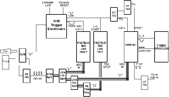
 Figure
7.5:
Schematic diagram of the electronics for the comparison of the DSM-performance
to a FASTBUS TDC and ADC. Some of the performance tests were done by varying
the attenuation (AT100) or the delay (after AT100) of the pulses.
One of the goals was the development of the software-code to compare the
DSC-waveform to commercial electronics modules: The obtained timing information
was compared to a FASTBUS TDC (FB TDC). The linearity of the amplitude was
tested relative to a FASTBUS ADC (FB ADC). Most of the tests described
subsequently were performed with NIM-pulses (logic "1"=-0.8V, "0"=0V). A
NIM-pulse triggers the event coincidence, which starts the TDC and creates the
GATE-pulses for the ADC and the DSM. The pulse is simultaneously used as an
"analog" INPUT signal for the TDC, ADC and the DSM (Fig. 7.5).
 Figure
7.6:
Display of a raw event after A/D conversion by the SIROCCOIII: The data of the
6 DSCs are converted serially (6·128 bins). The inputs of the 6 DSCs are
fast analog pulses of 10 ns FWHM and amplitudes of -80mV.
In order to perform measurements on timing resolution or amplitude linearity,
the delay or the attenuation of the "analog" signal was varied. After storing
one event, the FB ADCs, TDCs and the SIROCCO III were read out by the HIX
data-acquisition system [Rit 93].
The performance of the DSCs is illustrated in Fig. 7.6, where a raw event
consisting of 6 fast analog signals, after waveform digitizing, is displayed.
The sampling frequency is about 750 MHz, the rise times
tr of the recorded pulses are about 3 ns.


