Here is a diagram of the pion beta decay trigger electronics.
It is broken up into three pictures to make for more reasonable
image sizes.
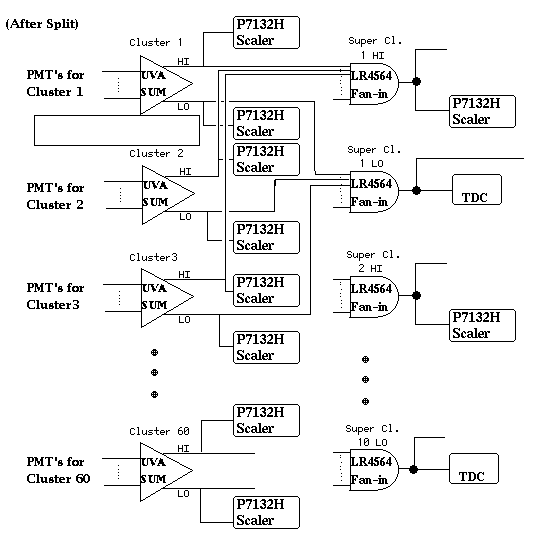
This is the section that forms superclusters from the individual
phototube signals from each crystal.

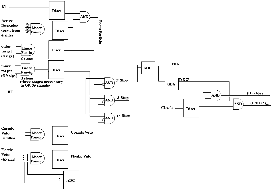
This part shows the formation of several other signals which may
be used in the trigger logic such as the delayed pion gate
a second delayed pion gate (prime) and a prescaled version
of each.

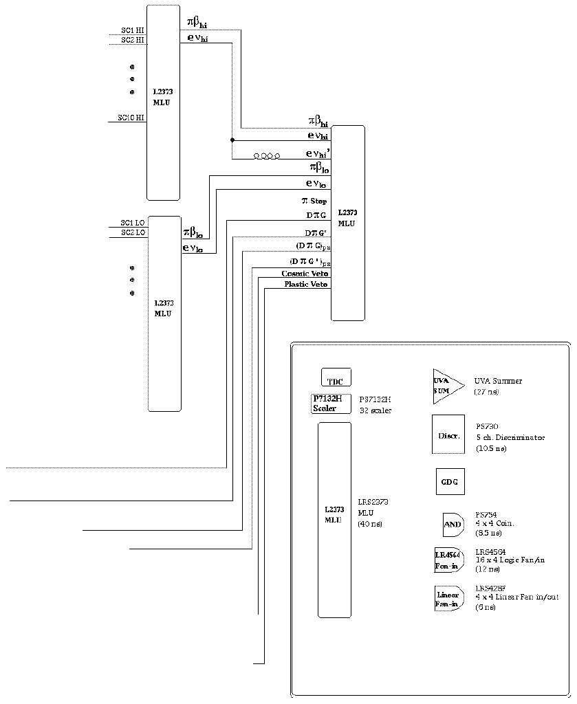
Here is where all the signals created in the two diagrams above
come into some programmable MLUs. The MLUs can be programmed
remotely to allow for changes in the trigger logic without having
to access the area.


