Pibeta trigger electronics '99
In '99, the pi-beta back-to-back logic has been replaced by a PSI LB500A
module featuring a Lattic ispLSI 2128E-LT165 chip. This field programmable
gate array (FPGA) contains about 6000 gates, which can combined in any
way through CAMAC programming. This unit replaces 6 modules from the '98
trigger (mainly 4518 fan-outs and 4516 logic units).
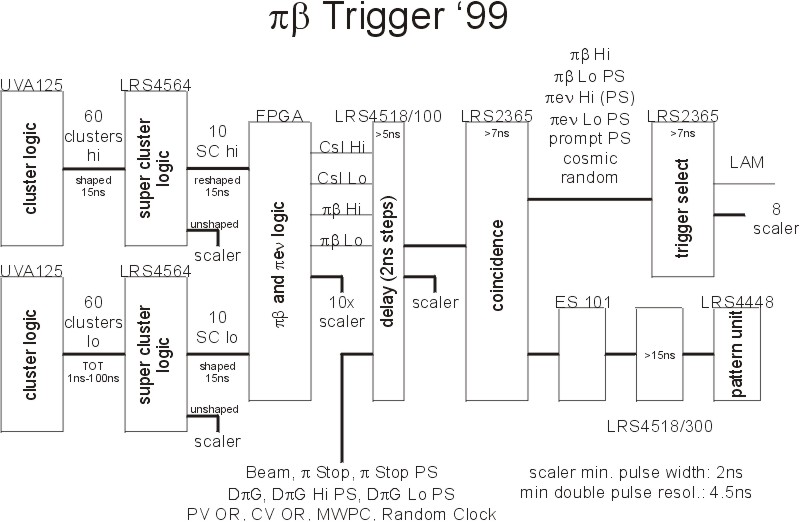
Here is the current proposal for the '99 trigger:

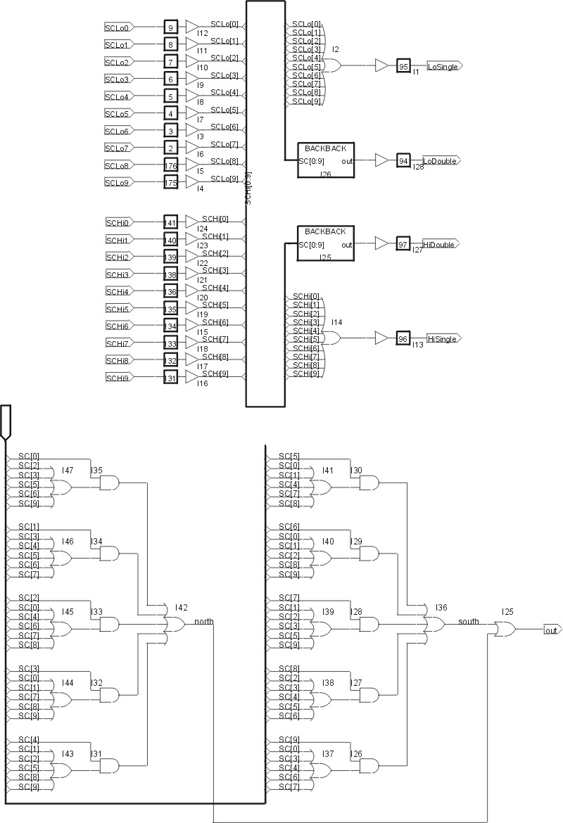
And the preliminary schematics inside the FPGA:
(The contents of the "BACKBACK" box is shown in the lower half)

A couple of minor changes have been made:
- The DpiG' has been dropped. Instead, we use a single delayed pion
gate, but with double width. The background events will be identified
by their TDC values.
- A cosmic and random trigger has been added. The random trigger will
be derived from a truely random clock, like a 1us delayes cosmic veto
signal.
- The shaper between the FPGA output and the LRS4518 input has been removed
since it was implemented with a analog discriminator which had a considerable
dead time. Since the shaped outputs of the LRS4564 are used, no reshaping is
necessary for the CsI Hi/Lo signal. The pi-beta signal can be shorter than
15ns since it is formed in an overlapped or between oppsite hemispheres.
Analysis of '98 data has shown that for correlated back-to-back events the
timing difference is +-5ns. SC signals with 15ns width having this jitter will
still produce an overlap signal of 10ns which can be well processed by the
following electronics.
- The scaler connected to the output of the LRS2365 coincidence unit was
moved behind the LRS2365 trigger select unit. This was due to the fact that
the trigger select unit needs a minimun input width of 7ns, while the
scaler accepts signals down to 2ns. It would therefore have counted
differently that the LAMs sent to the computer. By moving it after the
trigger select unit, it sees exactly the same pulses as the LAM. If a
overlap signal is shorter than 7ns, it is not passed through both to
the LAM and the scaler. In that case the gates at the coincidence unit
can be widened.
In a further step, the two LRS2365 can be replaced by a second FPGA module
once the logic inside these units is too limit to produce all our desired
triggers.

S. Ritt, March 18th, 1999


