Figure 1: Here you can see the alignment of the 300 mm wide scintillator pieces and the Wavelength Shifters.
The principal design is the same as for the top counter (see figure 1). The metal box is filled with scintillator paddels, 300 mm wide and on the upper and on the lower sides - parallel to the beam axis has each sidewall counter two wavelengthshifter bars. The wrapping is the same as for the top counter.
Figure 1: Here you can see the alignment of the 300 mm wide
scintillator pieces and the Wavelength Shifters.
Meanwhile we have received the missing parts to finish building up the
sidewalls completely: a few lighguides and the mechanical parts to
hold the PM tubes and to cover them lighttight, which have been
produced externally.

Figure 2: Workshop drawing for the PMT mechanics.
Figure 3: Workshop drawing for the PMT mechanics.
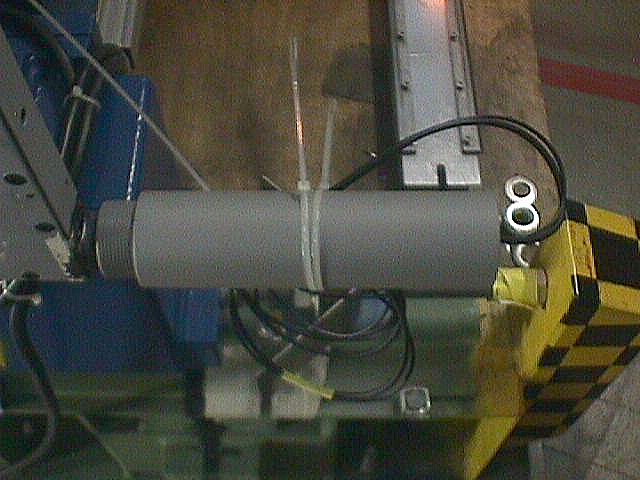
Figure 4: Lower PMT downstream beam right mounted.
We have decided to bring the PMT a little bit off by a lighguide extension under an angle of 10 degrees (see the drawing in figure 5 and the photograph in figure 6). The PMT will be mounted parallel to the Wavelengthshifter, not as shown as an alternative under this 10 degree angle which needs more space on the other side where we are limited too.
Figure 5: Search for the correct lighguide parameters - the angle
should not be higher to obtain good light collection efficiency. One
can see the green light coming out from the wavelength shifters (a
light is shining through from the other side).
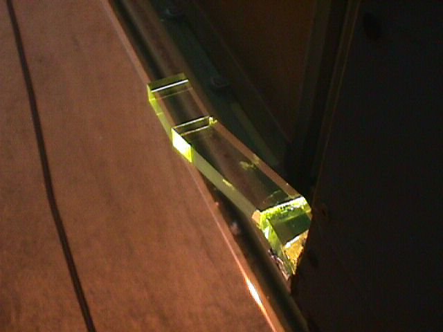
Figure 6: The lighguide extension from above after glueing it to
the WLS. One can see the green light coming out from the wavelength
shifters (a light is shining through from the other side).
On figure 6 one can see the interference between the counters. The sidewall PM would be mounted where you can see the Aluminium foil. The kind of mounting would be the same as for the
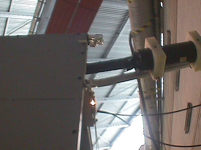
Figure 7: Interference between the meachanical parts of the readout of
the top and sidewall counters.
H.P. Wirtz , 11-Sep-2000
last update: 11-Sep-2000
Paul Scherrer Institut (PSI) WWW Information Services, Home
Page
Pion Beta Experiment Home Page
