![]()
In the 1999 fall beamtime the DSC CsI readout was tested. We found an indication for crosstalk on our ADC channels, which we have used as DSC input.
On the other hand the UVa splitter output is terminated with 50 Ohms; the twisted pair cable impedance is 100 Ohm (as the differential input termination of the ADC). This may cause reflections on these channels.
After our 1999 beamtime a first raw test was made by the input of a NIM pulse of one channel of the twisted pair cable and measuring its crosstalk on the neighbour channels. We could measure up to 15 percent of the original amplitude on the neighbour channels (analog scope, ground connection to the NIM pulser crate). The same test we have made with a sine signal (variation of frequency). Some crosstalk was measureable over the whole cable (8th neighbour). A big portion of this crosstalk was due to the use of the 'spy cards', which we use to split ECL signals. On the other hand we could see a huge noise on all channels.
The crosstalk was measured again without the use of the spy cards with an original CsI signal from channel CsI_02 (all other CsI high voltages are off). Figure 1 and 2 show scope hardcopies of the signals, channel 1 with the original signal, channel 2 shows crosstalk and noise on the neighbur channel. For figuure 1 a twisted pair cable is used, for picture 2 coaxial cables (RG174/U) with the same connector type with flat ribbon cable header.
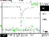
Figure 1: Crosstalk measurement with twisted pair cables
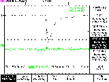
Figure 2: Crosstalk measurement with coaxial cables
The lower noise and lower crosstalk with 50 Ohm coaxial cables is also visible in our ADC spectra. For this mode a small modification on the ADC board is necessary. Then the ADC operates in 50 Ohm mode for coaxial cables instead of quasi differential input.
Figure 3 and 4 show the ADC spectra for CsI channel 2 with Cosmics. There is no significant difference between the two operation modes of the ADC.
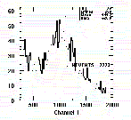
Figure 3: ADC Cosmic spectrum with twisted pair cables

Figure 4: ADC Cosmic spectrum with coaxial cables
By the use of coaxial cables we can reduce the noise by about a factor of 2. Figures 5 and 6 show the noise peaks with twisted pair cables and with coaxial cables.
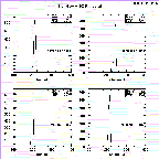
Figure 5: ADC pedestal peak with twisted pair cables
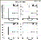
Figure 6: ADC pedestal peak with coaxial cables
Taking a look on the 2-dimensional Spectrum (Figure 7,8, CsI number versus ADC channels) it is obvious, that there is less noise on more or less all channels. There is more noise on these channels and maybe crosstalk over more or less all channels, because the twisted pair cables are packed very tight.
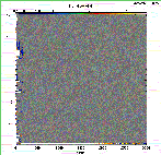
Figure 7: CsI channel versus ADC channel, Cosmic spectrum with twisted pair cables
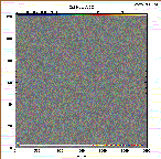
Figure 8: CsI channel versus ADC channel, Cosmic spectrum with
coaxial cables

H.P. Wirtz, 20 Jan 2000

Paul Scherrer Institut (PSI)
WWW Information Services, Home Page
Pion Beta Experiment Home
Page
