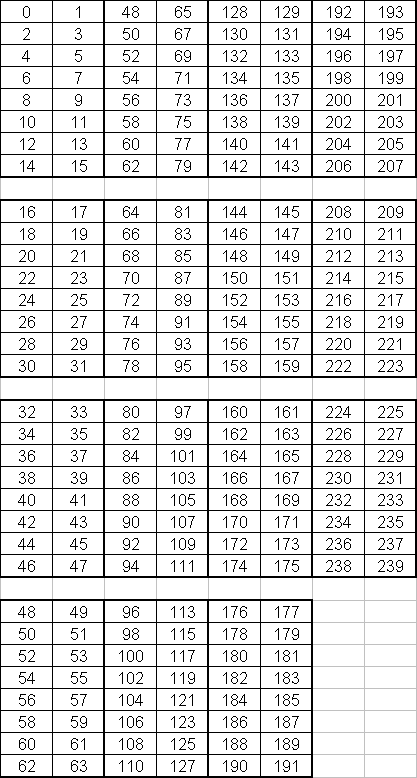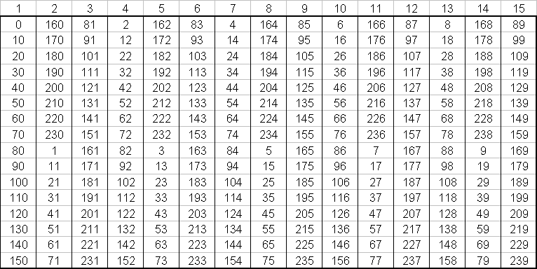
Cable Grouping: Both the trigger and delayed cables for the crystals are grouped in 15 bunches of 16 cables each. (Text File)

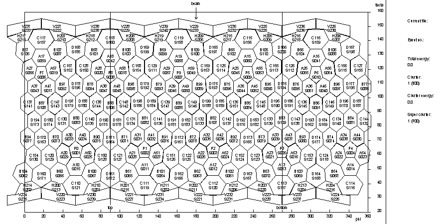
Cluster Definitions: Each cluster can be comprised
of up to nine crystals. The highlighted numbers show the crystals
that could be left out of the clusters with only a small effect on event
recognition.
(Postscript
File, Text
File)

Super Cluster Definitions: (Postscript File, Text File)
Trigger Splitters: Below is the organization for
the trigger splitters. Six splitter units have two rows of twenty
3x-splitters. The split signals go to the cluster units via
5ns limo cables according to the Cluster Definition table above.
Each cluster unit has inputs for four clusters. The cluster units
have two high threshold and two low threshold 10 pin ribbon cable outputs.
(Postscript
File, Excel
Spreadsheet) (Note: half-D splitters revised on January 23,
1999)
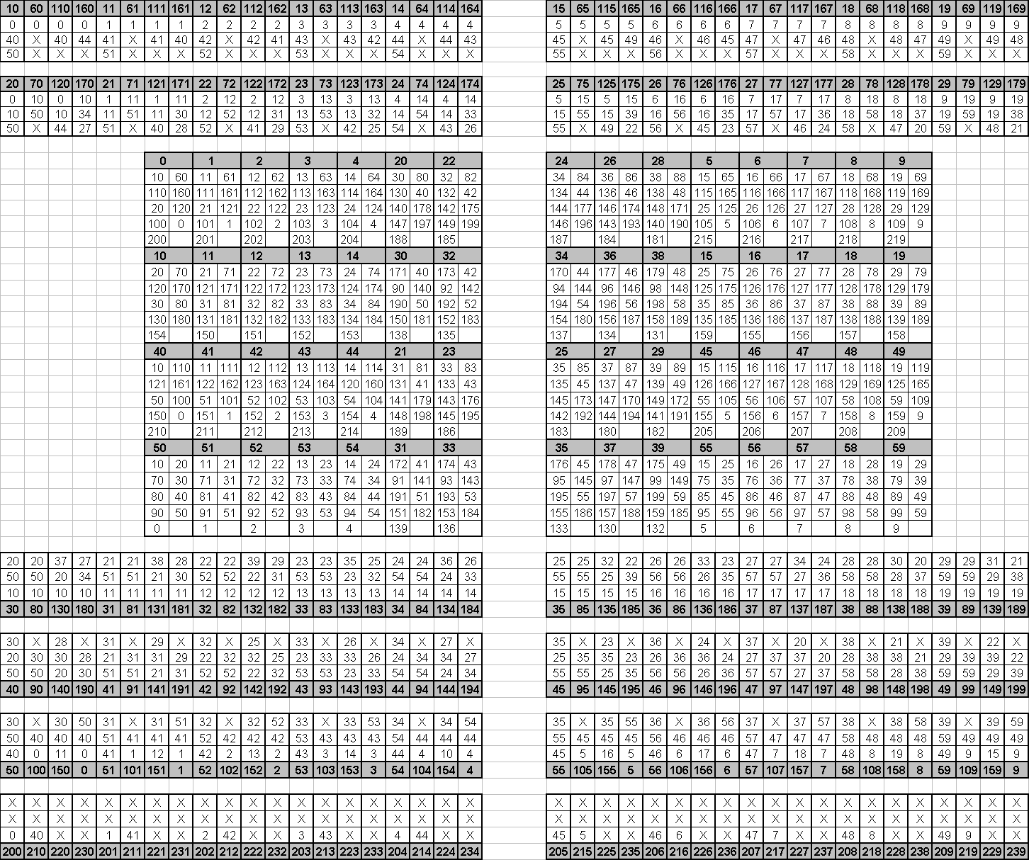
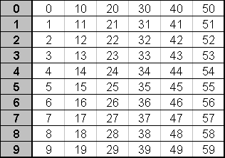
Delayed Splitters: Below is the organization for the slitters for the delayed cables. The signals going to ADC's and TDC's are ordered sequentially by crystal number. The splitters, grouped in units of sixteen, have special ribbon cable outputs which go to the ADC's. They also have limo outputs which go via 5ns limo cables to discriminators and subsequently to TDC's. This numbering system has the effect of separating neighbor crystals whereby a normal single arm event cause hits in two or less crystals from a group of 16 (four or less hits in a group of 32). This is very important for efficient readout of the Domino Sampling Chips. (Postscript File)
