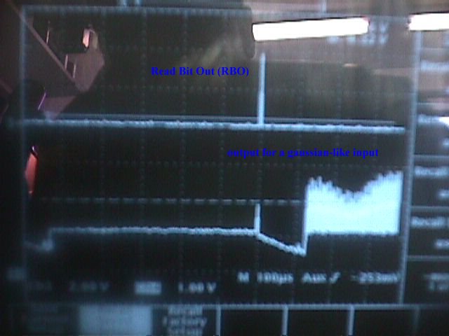
 Figure 1: DSC Output on Scope. You can see the Read Bit Out and the sampled
signal.
Figure 1: DSC Output on Scope. You can see the Read Bit Out and the sampled
signal.
From 517 chips 499 have been okay, which means 97% are working fine.
After cutting the chips (6 chips on 1 wafer), we have tested some of
them (random).
The complete worksheet of the chips you will find on the DSC Database .
We found out, that there is a spread (40 mV FWHM) of the threshold voltage (see figure 2), seen by the DSC comparator, which may cause trouble for the operation of the DSC.
 Figure 2: Threshold Voltages Histogram
This effect is just an offset from chip to chip, not linear. So it is
possible to adjust this threshold voltage for any chip individually (figure
3).
 Figure 3: DSC Threshold Voltage Linearity For 6 Different DSC


H.P. Wirtz, Dec-1998
last update 09-Aug-2000