

4.3.2 BEAM STUDIES WITH THE ACTIVE TARGET
In order to experimentally determine the beam parameters and the settings of
the magnets, beam line studies were performed in several test runs in 1992 -
1994. In 1994 the beam line was set up in the final geometry.
 Figure
4.4:
Pulse height (ADC value) in the active degrader B2 versus time (TDC start: B2;
TDC stop: RF-signal). A clear separation of the three different types of
particles is visible. The contaminations have been determined using box cuts on
these variables.
The active degrader B2 (40 mm thick scintillator) was put in front of the
active target, located at the focal point F at a distance of
1250 mm from the mirror plate of the quadrupole magnet QSK52. The
beam momentum was set to 116 MeV/c and optimized for pion stopping
rate in the target. For each incoming particle, the pulse height in B2 as well
as the timing relative to the accelerator frequency RF (50.63 MHz) was
recorded. This allows further elimination of beam muons and positrons. Fig. 4.4
shows how the different particle types can be identified; the resulting values
for the beam contamination with positrons and muons are listed in Table 4.1.
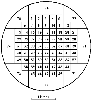
 Figure
4.5:
Cut through the active target used during the 1994 test run to measure the
horizontal and vertical beam profiles.
The active target is used to monitor the transverse stopping distribution. The
beam stopping distributions are needed for an accurate Monte Carlo simulation
of the experiment and acceptance corrections for pion beta and
p ->e+ n e decays. The present version of
the target consists of 69 plastic scintillator fibers surrounded by 8 guard
ring elements of the same material. It has a cylindrical shape of 4 cm
diameter and a length of 5 cm. Each of the fibers has a square cross
section of 2.76×2.76 cm2, and is covered with an acrylic
cladding of 0.12 mm thickness for optical insulation. A cut through the
active target is shown in Fig 4.5. Each of the scintillator fibers is connected
to a one inch photomultiplier tube via a fiber optic light guide.
A measurement of the beam stopping distribution is shown in Fig 4.6. Table 4.1
contains the main parameters of the beam measured with the active degrader and
the active target.
 Figure
4.6:
Two-dimensional beam stopping distribution measured with the active target. The
beam spot size given in Table 4.1 is determined by fitting the x and y
projections with a gaussian distribution.
|
Beam momentum
|
116
MeV/c
|
Momentum
acceptance
|
2%
(FWHM)
|
Rate
B1·B2[7]
|
|
5.5·105/s
|
Pions
|
4.3·105/s
(78.3%)
|
Muons
|
5.6·104/s
(10.2%)
|
Positrons
|
6.3·104/s
(11.5%)
|
Horizontal
beam size
|
1.3
cm (FWHM)
|
Vertical
beam size
|
1.0
cm (FWHM)
|
Table
4.1:
Beam parameters at the focal point F located 1250 mm from the mirror plate of
QSK54. The rates are obtained at a proton current of 0.8 mA.
[7] This is the coincidence rate of the counters B1
and B2


