

4.3.1 BEAM LINE
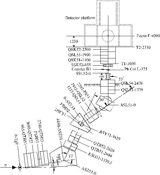
The p E1 beam line (Fig 4.2) supplies high intensity pion and muon beams with
momenta ranging from 10 to 500 MeV/c. The particles from target E are extracted
at an angle of 10° with respect to the proton beam direction. The desired
momentum of the channel is depending on the setting of the first dipole magnet
ASZ51. For the PIBETA experiment, the beam momentum of 116 MeV/c is chosen
as a compromise between pion rate, positron contamination of the beam and
separation of the beam particles due to time-of-flight (TOF) [5]
4.[4]
. At this momentum the beam is highly contaminated with positrons
(e+/ p + [congruent] 8, [Poc 89]) which induces
inordinate dead time and background counts in the detector. Proton, positron
and muon contamination of the beam is suppressed by moving the graphite
degrader plate DSC51 (4 mm) into the beam trajectory. Protons are stopping in
the degrader. For 116 MeV/c the pion and positron momenta are reduced by 25
MeV/c and 1.7 MeV/c respectively. This results in different deflection angles
in the dipole magnets ASY51 and ASL51 and thus in a positional displacement at
the lead collimator L for the different particle types. The lead collimator L
with a circular opening of 10 mm diameter thus reduces the positron
contamination of the beam by about 2 orders of magnitude. The scintillator B1
(1 mm thick) is located right after the lead collimator and counts the
remaining beam particles.
The additional beam line elements in the p E1-area are the quadrupole magnets
(quadrupole triplet) QSK51, QSL55 and QSK52 and a vertical (SSL51) and a
horizontal (SSK51) steering magnet. The momentum bite of the beam is 2%.
 Figure
4.2:
The p E1 beam line. The location of the detector platform is indicated. In
the first part of the 1994 beam time, the beam line was set up with an active
degrader B2 in front of the active target at the focal point F. The numbers
after the names indicate distances in mm.
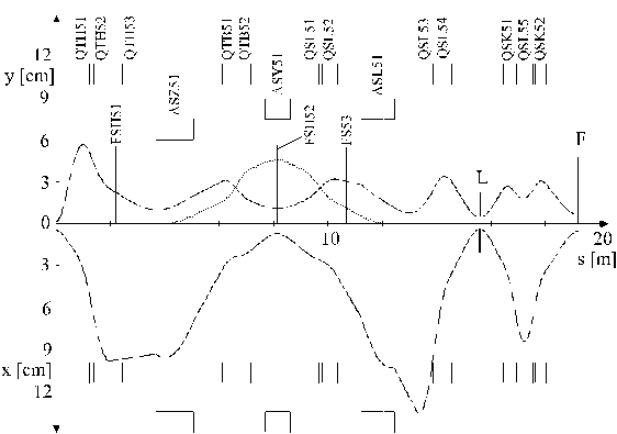
The beam envelope for the p E1 channel calculated by the program TRANSPORT
[Bro 73] is shown in Fig. 4.3. The solid curves correspond to the horizontal
and vertical envelopes of the beam. The main features of the beam tune are as
follows:
a) Maximum momentum dispersion and a double waist in the dipole magnet ASY51.
b) Narrow waist in both horizontal and vertical direction in the lead
collimator L.
c) The waist in L is imaged onto the focal point F by the quadrupole triplet
QSK51, QSL55, QSK52.
d) Beam spot size of about 1 cm diameter in both vertical and horizontal
direction. This ensures that the beam is almost fully contained in the target.
 Figure
4.3:
Graphical ouput[6] of a TRANSPORT
calculation for the p E1 beam line with elements as shown in Fig 4.2. The
upper part shows the vertical envelope y, the horizontal envelope x is shown in
the lower part. The dashed line is the dispersion trajectory i.e. the
horizontal trajectory of a particle with a deviation from the nominal momentum
of 1% .
[5] Kinetic energies of p 's,
µ's and e's at 116 MeV/c are 42 MeV ( b =0.36),
51.3 MeV ( b =0.44) and 116 MeV ( b =1) respectively. The
TOF separations at the channel length of 19.6 m are maximal at this
momentum: 2.5 ns between p 's and e's , 6 ns between
p 's and µ's respectively (see Fig. [ for the measured diffe]rences)
[6] The computer program for a graphical
interface to the transport program was written by U. Rohrer (PSI).


