

The five triggers were:
* CsI high threshold in DPG
* CsI high threshold in DPG'
* CsI low threshold in DPG
* CsI low threshold in DPG'
* Prompt event in CsI
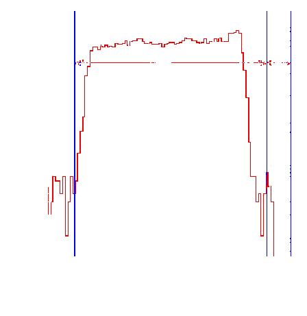
Events where one or more CsI crystals were hit during the DPG contained most of the p -> e n ( g ) events, while those where one or more of the CsI crystals were hit during the DPG' provided a measurement of the background. Figures 5.2 and 5.3 show the high and low threshold energy spectra (as seen by the CsI), respectively. The timing of the event was best characterized by the degrader time, because the trigger timing (and thus, TDC start) was determined by when the CsI crystals were hit. The "clocks" were therefore started when a decay occurred while the degrader timing correlated strongly with the beam particle timing. Figure 5.4 shows a degrader timing spectrum for pion decay events.
The prompt trigger was used to get a measurement of the background produced by beam related processes. One such process is scattering particles from the target contained in beam buckets subsequent to the one that created the trigger. These processes happened on the hadronic time scale (less than 0.1 fs). These prompt events

Figure 5.2: CsI sum spectra with high energy threshold. The plot on the left is from events in which the CsI was hit during the DPG. The plot on the right is from events in which the CsI was hit during the DPG'.

Figure 5.3: CsI sum spectra with low energy threshold. The plot on the left is from events in which the CsI was hit during the DPG. The plot on the right is from events in which the CsI was hit during the DPG'.
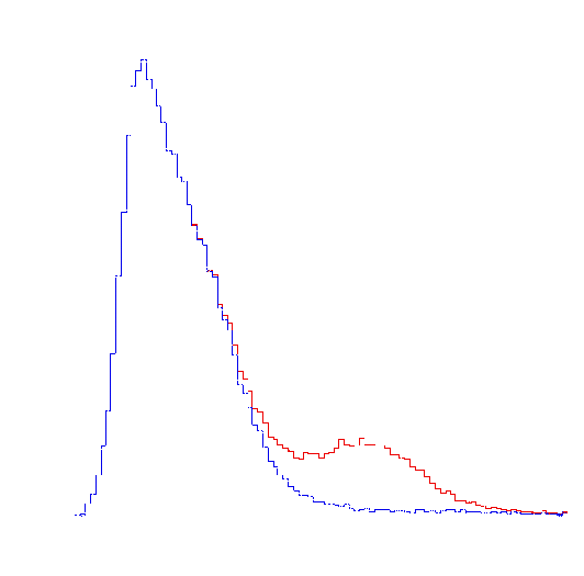
also tended to have high energy signals in the target. Figure 5.5 shows a target energy spectrum for DPG events with the target energy spectrum for DPG' events overlaid Figure 5.6 shows a histogram of the time between the degrader signal and a signal from the CsI calorimeter made from events caused by the prompt trigger. The beam rate of 20 ns per bucket is clearly visible. Figure 5.7 shows a similar plot made from events occurring in the DPG but with a cut on the target pulse height containing greater than 700 channels (see Figure 5.5).
Data also were taken using a 70 MeV positron beam. For these runs, the target was removed, the CsI calorimeter was rotated directly into the beam, and the beam was defocused so as to illuminate a number of crystals simultaneously. Figure 5.8 shows a

Figure 5.4: Timing spectrum for events in the DPG. Time increases to the left and the TDC start is at approximately channel 100. The variables d and w represent the delay and width of the DPG respectively.
Pulse height spectrum resulting from this data. The purpose of running in this altered state was to measure the CsI response to positrons similar to those produced in p -> e n decays.

Figure 5.5: Pulseheight spectrum for the target for events in the DPG and DPG'. The bump at high pulseheight is due to prompt events which form part of the background. Events measuring more than 375 ADC channels in the target were discarded.


