

 accounts for the Michel decays with very low energy positrons that were too
weak to produce a valid trigger and were therefore not recorded during the
experiment. This correction uses an estimate of the missing low energy Michel
events based on fitting the theoretical Michel curve to the measured positron
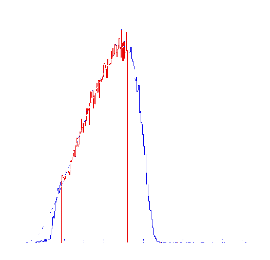
energy spectrum for positron energies above 10 MeV in the CsI. Figure 5.13
shows a plot of the low energy Michel spectrum with the theoretical curve
overlaid. The

| d
\ w
|
73.0
ns
|
74.0
ns
|
75.0
ns
|
76.0
ns
|
77.0
ns
|
| 9.0
ns
|
20.10
|
19.91
|
19.72
|
19.53
|
19.35
|
| 9.5
ns
|
19.93
|
19.74
|
19.56
|
19.37
|
19.12
|
| 10.0
ns
|
19.77
|
19.58
|
19.39
|
19.21
|
19.03
|
| 10.5
ns
|
19.60
|
19.41
|
19.23
|
19.04
|
18.87
|
| 11.0
ns
|
19.44
|
19.25
|
19.06
|
18.88
|
18.71
|

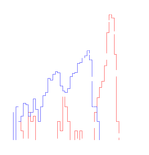
Figure 5.12: Timing spectra used to determine gate delay
 .
Time increases to the left. The prompt trigger events (red) show where the TDC
start is (i.e. time=0). The right edge of the DPG event histogram (blue) show
where the DPG starts. The difference between the two is the delay
 after the pion stop before the DPG opens.
sum CsI spectrum was shifted by 2.0 MeV (73 ADC counts) to account for energy
lost in the target. The experimental spectrum contains
 events below channel 470 (~10 MeV in CsI) while the area under the theoretical
curve is
 in this same range. The total number of events in the experimental Michel
spectrum is
 .
.

Figure 5.13: Low energy end of experimental Michel spectrum with theoretical curve. This spectrum was shifted up by 73 ADC channels to account for the ~2MeV lost in the target.
The correction
 is then given by

where the uncertainty comes from the statistical uncertainty of
 and
and
 .
.


