

Next: Results of Light Output
Up: Cosmic Muon Tomography Results
Previous: Cosmic Muon Tomography Results
The first step in the data reduction for light nonuniformity calculations
with the CMT device, after pedestal subtraction and gain matching,
is to describe the geometry of the scintillator in the reference frame of
the dark box. This information is needed in order to translate the
wire chamber trajectories into particle entry and exit points in the
scintillator volume, which are then used to calculate the muon pathlength.
The CMT coordinate system is shown in Figure 3.7, with
six CsI crystals and photomultiplier tubes appropriately positioned.
Figure: Coordinate system of CMT apparatus with six CsI crystals
and photomultiplier tubes in place. The two coordinate
systems shown correspond to the left three crystal positions and the right
three crystal positions, respectively.
From the figure, one can see that there are actually
two coordinate systems; one for the three crystals on the left, and one for
the three crystals on the right. In this way, the positive z-axis always
points from the narrow front face of the crystal, to the wide back face.
As a check in the
geometry, one can plot the reconstructed muon entry and exit points in
the three orthogonal planes to see that they form the outline of the CsI
crystal volume.
Figure 3.8 shows these plots for one hexagonal CsI crystal.
Figure 3.7: Reconstructed entry and exit points of cosmic muons in
one CsI crystal.
Finally, using the calculated
pathlength and the ADC value for each event, one can determine the
average light output per unit pathlength integrated over the trajectory
defined by the entry and exit points.
The light output per unit pathlength can be plotted along the
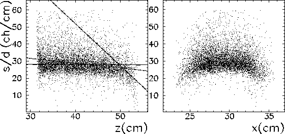
axes of the crystal. Figure 3.9 shows the light output per unit
pathlength (`s/d') along the longitudinal (z) and transverse (x) axes
for two CsI crystals. To represent the longitudinal light nonuniformity of
the crystal, the graph has been fit with straight lines in three separate
regions: the front 10 cm of the crystal, the middle 8 cm, and the
back 4 cm. These boundaries have been chosen by inspection of apparent
discontinuities in the nonuniformity spectrum.
The slopes of the fitted lines, divided by the average value of
the light output per pathlength in the region of interest, represent the
spatial nonuniformities of the light output for the crystal in percent
per centimeter.

Figure 3.9: Light output per unit pathlength as a function of the longitudinal
(left panel) and transverse (right panel) average crystal
coordinate, for one hexagonal CsI crystal. The longitudinal nonuniformity is
quantified with the slopes of three straight lines (shown), which are fit to
the plot in three predetermined regions.
The fitting algorithm used is a ``maximum likelihood'' method [16].
A chi-squared
fitting routine was also tried, but was not successful due to the influence
of a small number of points which were much higher than the majority.
The maximum likelihood method minimizes the sum of the absolute deviations

where  are the parameters which describe the fit
to the data set
  .
In comparison, the chi-square method minimizes the quantity

where  is the standard deviation of each measurement
  .
The maximum likelihood method is useful in cases where a Gaussian model
for measurement errors is a bad approximation. It assumes that the
measurement error is the same for all data points, thereby minimizing
the influence of data points which deviate greatly from the
majority of the measurements.
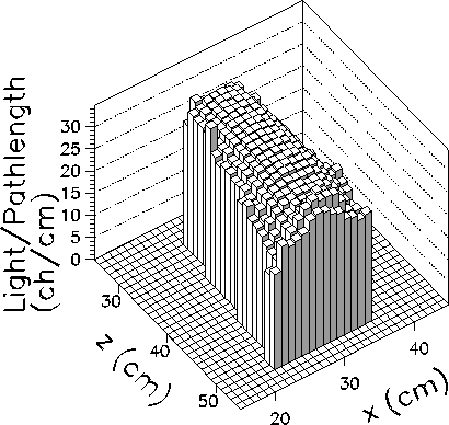
To visualize the light output distribution qualitatively, one can make a two
dimensional histogram of the light output per pathlength as a function of
the axial and transverse coordinates. Figure 3.10 shows such a
histogram for one hexagonal crystal.

Figure 3.9: Two-dimensional light output per pathlength of one
hexagonal CsI crystal, projected onto the horizontal plane.


Next: Results of Light Output
Up: Cosmic Muon Tomography Results
Previous: Cosmic Muon Tomography Results
Penny Slocum
Fri Apr 2 00:36:38 EST 1999


