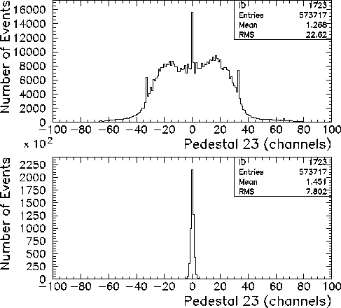
Figure 4.1: CsI Pedestal spectra before and after second pedestal subtraction algorithm has been implemented.
Following the first (absolute) pedestal subtraction, a second pedestal subtraction algorithm is implemented to remove low energy common mode noise from the data. The second pedestal subtraction algorithm works as follows:

Figure 4.1: CsI Pedestal spectra before and after second pedestal subtraction algorithm
has been implemented.
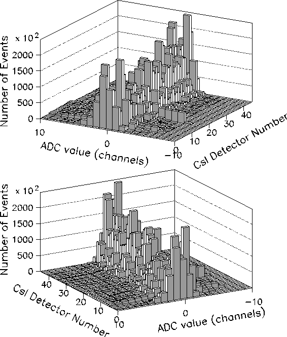
Figure 4.2 shows the 44 CsI pedestal spectra, after the first and second pedestal subtraction have been implemented.

Figure 4.2: Final CsI pedestal spectra after both first and second pedestal
corrections, viewed from two different angles.
By inspection of this histogram, one can see that a summing threshold of ![]() channels
(0.2 MeV)
can be chosen to separate noise from data. All CsI ADC values which are below
channels
(0.2 MeV)
can be chosen to separate noise from data. All CsI ADC values which are below
![]() are considered to be noise and are ignored, while all that are above
are considered to be noise and are ignored, while all that are above ![]() are summed as data.
are summed as data.
The first and second pedestal subtraction algorithms are also applied
to the 64-element NaI array, after which one can safely select
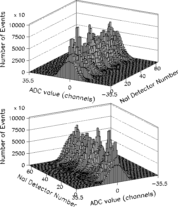
![]() channels (0.4 MeV). Figure 4.3 shows the 64 NaI pedestal
spectra after the first and second pedestal subtractions.
This discrepancy between
channels (0.4 MeV). Figure 4.3 shows the 64 NaI pedestal
spectra after the first and second pedestal subtractions.
This discrepancy between ![]() and
and ![]() is due to the fact that the ADC
gate width for the NaI detectors was longer (800 ns) than that of the CsI detectors
(100 ns). Hence, more low energy noise was integrated by the ADC for the NaI channels.
is due to the fact that the ADC
gate width for the NaI detectors was longer (800 ns) than that of the CsI detectors
(100 ns). Hence, more low energy noise was integrated by the ADC for the NaI channels.

Figure 4.3: Final NaI pedestal spectra after first and second pedestal
corrections, viewed from two different angles.
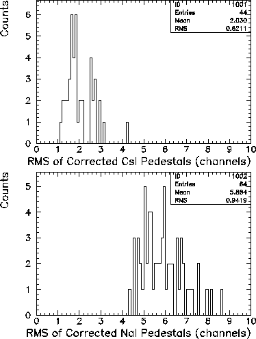
Finally, one can see the root mean square values for the corrected CsI and NaI
pedestal histograms in Fig. 4.4. The root mean square value
![]() is calculated as
is calculated as

where ![]() is the ADC value of the ith bin in the pedestal histogram,
is the ADC value of the ith bin in the pedestal histogram, ![]() is
the mean, and N is the total number of events.
is
the mean, and N is the total number of events.

Figure 4.4: Root mean square ![]() values of the corrected CsI and NaI
ADC pedestal histograms.
values of the corrected CsI and NaI
ADC pedestal histograms.