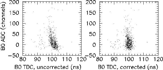
Figure 7.4: B0 beam counter ADC value plotted against the B0 TDC value, before (left panel) and after (right panel) slewing correction.
An important step in the data analysis is to correct for slewing in the timing of the beam counter and the CsI detectors. The B0 beam counter slewing can be observed by plotting the B0 ADC against B0 TDC, as shown in the left panel of Fig. 7.4. The slewing is caused by the dependence of the B0 detector discriminator response on the B0 ADC pulse height. It is revealed by the amplitude-dependent timing of the data points in the scatter plot. In order to correct for the slewing, a function is devised to fit the graph and calculate the deviation from a fixed timing offset for every B0 ADC value. The best correction function was found to be a piece-wise straight line, positioned onto the scatter plot by naked-eye inspection. The resulting plot, following the slewing correction, is shown in the right panel of Fig. 7.4.

Figure 7.4: B0 beam counter ADC value plotted against the B0 TDC value, before
(left panel) and after (right panel) slewing correction.
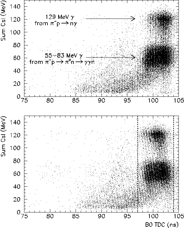
The time slewing in the CsI crystal TDC's is evident from the scatter plot in the
top panel of Fig. 7.5, showing the sum of the CsI ADC values plotted against
the B0 TDC.
By inspecting the graph, one can see that the 129 MeV photons from the pion capture
reaction ![]() appear
appear ![]() ns later in the
B0 TDC spectrum than do the box spectrum of photons. This timing difference is caused
by the fact that
the CsI discriminators start the TDC for every event. The slewing results from a spread in the
TDC start times based on the differing pulse heights from the individual CsI detectors.
The corrected scatter plot, shown in the bottom panel of Fig. 7.5, is obtained by
fitting a straight line to the uncorrected two-dimensional histogram in the top panel
of Fig. 7.5, and using this line
to calculate the deviation from a fixed time for every value of the sum of the
CsI ADC values.
ns later in the
B0 TDC spectrum than do the box spectrum of photons. This timing difference is caused
by the fact that
the CsI discriminators start the TDC for every event. The slewing results from a spread in the
TDC start times based on the differing pulse heights from the individual CsI detectors.
The corrected scatter plot, shown in the bottom panel of Fig. 7.5, is obtained by
fitting a straight line to the uncorrected two-dimensional histogram in the top panel
of Fig. 7.5, and using this line
to calculate the deviation from a fixed time for every value of the sum of the
CsI ADC values.

Figure 7.5: Sum of 44 CsI ADC values plotted against the B0 TDC, before (top panel)
and after (bottom panel) slewing correction for the single arm trigger configuration.
Only events whose B0 TDC values are greater than 97 ns and less than 104 ns (dotted lines)
are used in the
extraction of the Panofsky Ratio value. Charged particle events are vetoed by the
plastic hodoscope.