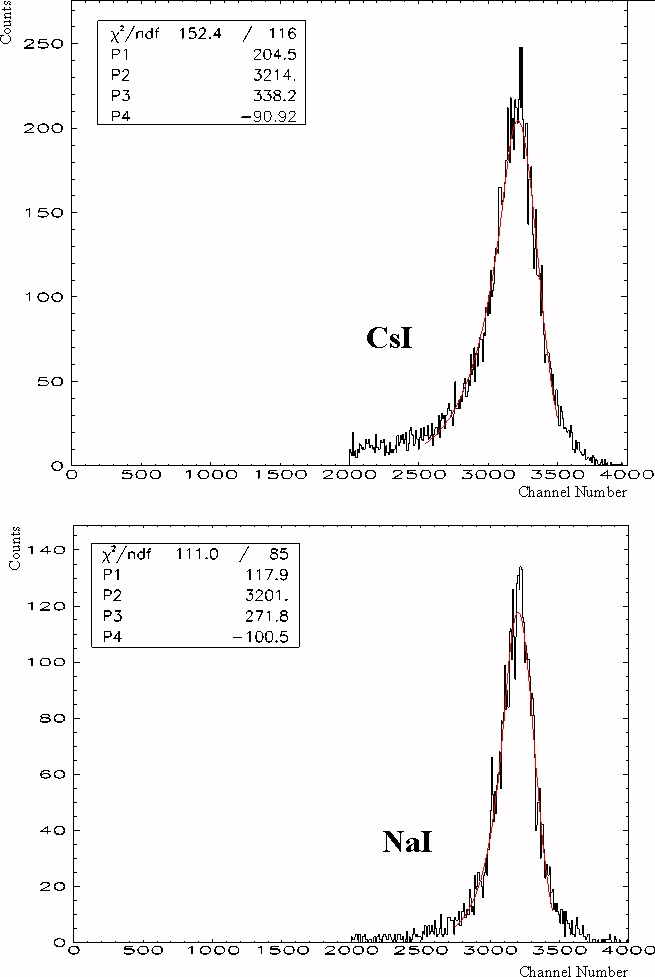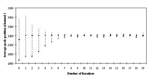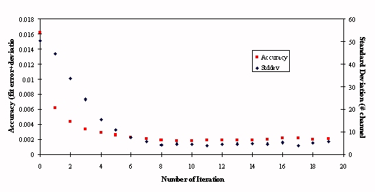


The gain matching routine was programmed to shift the i-th sum spectrum to channel 3206, the equivalent to the energy of the p 0 (137.8 MeV). Then summing accomplished in using equation 7.a, but having N=108. The spectrum was cut arbitrarily at channel 2000, since the peak position was the only relevant information. Due to the high numbers of channels to add up, more iteration compared to the on-line gain matching was necessary. The actual values of the p 0-peak were determined in the first pass and a software gain factor was calculated. In addition the pedestals were fitted with a Gaussian and then readjusted in the database, if necessary. In subsequent iterations the software gains of individual modules were adjusted.


Finally, the procedures converged after about a dozen iterations, as seen in the preceding figures. The iteration was continued until either all channels were matched with the required accuracy or neither the average peak-position nor the total error could be improved. For the case of results floating around a minimum, the iterative process was ended after 32 iterations. Then the best obtained result was written to the database file. An average peak position at channel 3206 with a standard deviation of better than 5 channels (or 0.2 MeV) was obtained for all relevant runs.
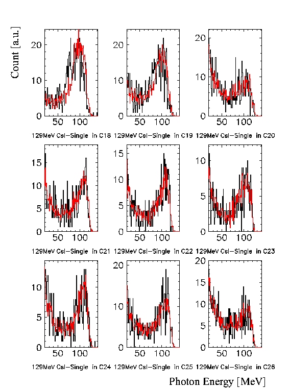
A set of reference histograms was established for the second step with the above mentioned GEANT code. The objective was a direct comparison of the simulated and measured crystal responses. To this end the RC events were selected by allowing only events, when the sums of all crystal channels exceeded 86.3 MeV. In the simulation 129 MeV photons were thrown uniformly onto the detector arrays. Histograms for each channel were established with the same energy constraint as for the data reference and stored as ASCII files. After the data histograms were generated, they were compared with the reference histograms using the minimum c 2 method. Software gains in ranging from 0.85 to 1.2 were applied to the data histogram until the best match to the reference histogram was achieved. The obtained software gains for each run were stored in database files for further use in analysis. Repetitive runs with the obtained software gains showed that the spectra would not need further adjustment as a visual inspection can demonstrate (Figure 7-7). The outermost NaI modules were not included in this procedure because they had to act as a veto if their sum energy exceeded about 2 MeV.

. Finally, the sum of the energy deposited in the array was built and consequently the simulated 129.4 MeV peak was used for calibration, because the individual spectra could be matched that well. In order to test for gain linearity a second energy reference was considered. This was the centre of the photon distribution from the p 0-decay, which is positioned at 68.9 MeV. In order to obtain this centre the edges of the distribution were used. Since the theoretical box distribution is smeared in the same way as a monoenergetic peak, the left side was fitted with an exponential curve and the right with a Gaussian. Then the midpoints of the two edges were defined as the position where the functions reached the value of half the distribution maximum. Finally, the centre was calculated as the arithmetic mean of the two midpoints. For an example of this fit see section 7.5 .


