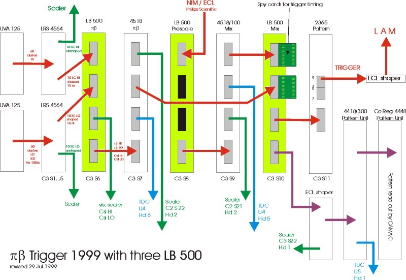
Following picture gives an overview of the revised trigger scheme. Red paths mark signal flow of the trigger, which is time-critical, green are scaler signals and blue are TDC signals. Click on individual LB500's to see internal programming and pin assignment.

This schematics is also available in EPS format.