 Zero Suppression Mechanism
 Zero Suppression Mechanism
As discussed in the previous sections, a multy channel DSC application without any Zero Suppression is not feasible, since the dead time of the system and the amount of data for each event would be enormous.
On each DSC there is, beside the sampling part, a Zero Suppression circuit.
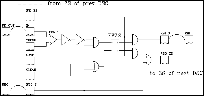
The principle of the ZS mechanism is to read out only those DSC channels which are
carrying significant pulse information: The input pulse must be above a user defined threshold and
within a user defined time gate (see Fig. 1). If both of these requirements are fullfilled, the
FFZS is set and pointing at the RBI pad of the sampling part of that particular
DSC. If one or both of the requirements are not fullfilled, the RBI pulse is pointing directly
at the output of the ZS, the RBO ZS, which is connected to the ZS of the next DSC. Whenever the
read out phase is started with a RBI, the "route" of the RBI pulse is allready prepared, i.e. it is
defined which DSC's are read out and which are not.

Fig. 1: Zero suppression circuit on the DSC
Fig. 2: Block diagram of the DSM100 board

.
Ch. Broennimann, 6. Jan 1995