

The optical properties of a crystal can be influenced by wrapping the side faces and covering the front face. Different wrapping materials were tested for maximal light output and minimal optical non-uniformity. Best results were obtained by wrapping the crystal with three layers of teflon-foil (total ~60µm thick) and one layer of aluminized Mylar (~20 µm) for optical insulation. Additional beam studies were performed to check the influence of the front face coverage on the light collection non-uniformity. Covering the crystal front-face with black paper turned out to be the optimal solution.


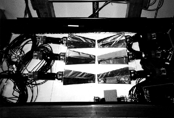
For a cosmic muon penetrating the apparatus, the hits in the 3 chambers allow a precise determination of the track. The segments of the cosmic ray paths in the CsI-crystals can be calculated and compared to the actual crystal signal. Only muons penetrating the crystals in almost vertical direction (polar angle q >85°) are accepted. This allows the determination of the light per unit pathlength along the crystal axis (axial, z-coordinate) and perpendicular (transversal, x-coordinate) to the crystal axis. The resulting light non-uniformity from this 2-dimensional reconstruction procedure for one CsI-crystal[13] is shown in Fig 5.9.
The cosmic ray tomography is a delicate project. It needs very careful tuning and calibration of the experimental apparatus as well as an elaborated analysis of the data. The quality of the data and their analysis are currently improved. The aim of the analysis is the quantification of the light non-uniformity for each crystal. Since the final data for each crystal was not available as the writing of this work was ongoing, only common features of the optical response as they are visible in Fig 5.9 can be given:
* bright spot at the front face (z = 0-5 cm) of the crystal.
* a "hole" in the response at z ~ 15-18 cm, where the light output is ~10-15% lower.
* bright zone at the back face in front of the PMT (z = 22 cm)
* dark zones at the edges of the crystal.
In order to incorporate the optical response in the simulation of the
electromagnetic shower, it is parametrized by an analytic function
flnu(r,z) which approximates the features listed above. The
light non-uniformity function flnu(r,z) (Fig. 5.10) is
calculated for each space point x, y, z in the body coordinate system of
the volume of a crystal, with
 :
:
The length of the crystal is l=22 cm, the "hole" in the response is assumed to be at zd=15 cm. The parameter lnu corresponds to the difference between the light output at z=0 and zd of the crystal. The parameters PF and PB account for the transverse non-uniformity at the front and back of the crystal, which is assumed to be parabolic. Best correspondence with the experimental data available was obtained with PF=0.002, PB=0.02 and lnu=0.12.

 (5.10)
is constrained as follows:
fz (z=0) = 1; fz (z=zd) = 0; fz (z=l) =-1. (5.11)
The resulting parameters are:
 .
(5.12)
It should be mentioned that (5.9) represents a first approach to parametrize the optical non-uniformity of the crystal. The function flnu(r,z) is likely to change with the improved analysis of the tomography data. The aim of the tomography project is the parametrization of the optical response of each crystal in the pibeta calorimeter.


