

Next: Design of the
Up: Overview of the
Previous: Shower Calorimeter
The mechanical support of the detector apparatus with the requirement of
easy access to inner detectors (the target, the MWPC's and the plastic veto)
and upstream detector readouts, has been designed and at the time of this writing,
parts of the support structure are under construction. Except for the
cosmic veto house, the entire detector apparatus including the electronics is
supported on a platform and can be craned in and out of the experimental area
( area). The veto house consists of a frame with layers of lead bricks
and the cosmic veto detectors on the outside of the frame. The bricks prevent
self-vetoing in the cosmic veto detectors due to leakage of showers
through the back faces of the calorimeter modules. The veto house is equipped
with a rail system on the platform and can be wheeled in to enclose the rest
of the apparatus on all sides except upstream from the beam where there is a
concrete wall for the shielding of the detectors from beam related events,
and on the bottom where the platform is. The veto house can also be wheeled
out up to five meters, thereby exposing the thermal house around the
mechanical support of the calorimeter
 .
.

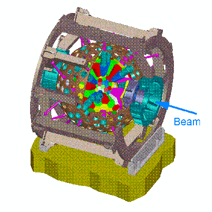
Figure: The support structure of the
calorimeter showing the spherical steel housing, the inner calorimeter modules,
the metallic cylinders enclosing the PMT's and the mechanical frame holding the
housing.
The thermal house and the support of the calorimeter are equipped with their
own rail system and can be wheeled out (downstream of the beam) up to 85 cm
for easy access to the upstream detectors such as the beam counters, the
active degrader, etc. The support of the calorimeter consists of a spherical
metallic housing with holes within which fit metallic cylinders enclosing the
PMT's of the calorimeter modules. The spherical housing is in turn held by a
mechanical system as shown in figure  . The housing is made of
steel plates that have been forced into semi-spherical geometry to create two
hemispheres which are then welded. The support of the twenty plastic veto
staves is provided by a thin (one millimeter) carbon fiber cylinder which
protects the outer MWPC. The carbon fiber cylinder also provides for smooth and
easy insertions and removals of the outer chamber which is equipped with
flanges and step-down rings for the support of the inner MWPC (figure 5.1).
The target has its own support system with rails and can be wheeled in and
out separately. This facilitates the interchange of the passive and the active
target during the data taking process.

Figure: The truncated
trapezoidal pyramid VT1. These are the edge shower veto detectors. There are 10 of
these modules. In the process of the geodesic breakdown, this shape was produced as
one HD plus one quarter of hexagon C.

Table: Properties of the trapezoidal
pyramid VT1. The coordinates of slanted faces in figures  and
and  are indicated by the
  .
.

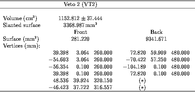
Figure: The truncated
trapezoidal pyramid VT2. These are
the other edge shower veto detectors. There are 10 of these modules making a
total of 20 shower vetoes. VT2 is a mirror symmetry of VT1. To avoid an interference
between the plastic veto detector and the shower vetos, the orginal geometries VT1 and
VT2 were trimmed to produced the slanted faces shown figures  and
and  .
.

Table: Properties of the trapezoidal
pyramid VT2.


Next: Design of the
Up: Overview of the
Previous: Shower Calorimeter
Bernward Krause
Mon Jan 15 14:57:06 MET 1996
 area). The veto house consists of a frame with layers of lead bricks
and the cosmic veto detectors on the outside of the frame. The bricks prevent
self-vetoing in the cosmic veto detectors due to leakage of showers
through the back faces of the calorimeter modules. The veto house is equipped
with a rail system on the platform and can be wheeled in to enclose the rest
of the apparatus on all sides except upstream from the beam where there is a
concrete wall for the shielding of the detectors from beam related events,
and on the bottom where the platform is. The veto house can also be wheeled
out up to five meters, thereby exposing the thermal house around the
mechanical support of the calorimeter
 .
.


 .
.
