 ). A temperature sensor is also installed in
the box, and for every event during the data taking process, the temperature
and the absolute time are also read out.


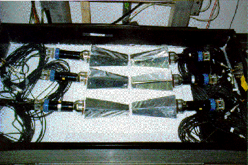
Six crystals at a time can be positioned in the box after they have been
carefully prepared, i.e., polished, wrapped in three layers of teflon and
one layer of aluminized mylar with black paper on the front face, and PMT
glued (figure  ). A temperature sensor is also installed in
the box, and for every event during the data taking process, the temperature
and the absolute time are also read out.

Figure: Positions of crystals in the tomography
apparatus.
Once the modules have been positioned, and their identities, positions and
orientations recorded, the box is closed and light proof. The apparatus is
operated in a climatized room with controlled humidity. The crystal PMT's and
the drift chambers are then brought under their operational voltages for a
day or so before the data taking. The operational voltages of the PMT's are
determined by requiring that the minimum ionizing peaks fall in the same
channels. For the drift chambers, positive high voltages of 2200-2400 Volts
are applied to the anode wires with the cathode wires grounded. These drift
chambers were built at the Los Alamos Meson Physics Facility (LAMPF) and
were previously used in other experiments [Ate-81], [Mor-82],
[Ran-81] and [Ran-82]. Each
chamber has two signal planes and three ground planes on each side and
in-between the signal planes which consist of two orthogonal sets of
alternating anode and cathode wires. The anode-cathode separation is
0.4064 cm. The cathode wires are alternately attached to two bus lines,
thereby making an odd (O) and an even (E) bus lines. The anode wires are
soldered onto a delay line of 2.0 ns per wire spacing, i.e., a total of
144 ns for each anode line containing 73 wires. A gas mixture of  argon,
  isobutane and
  isopropyl is supplied to the chambers.
The gas pressure in the chambers is kept constant over time via a bubbler
with 3 mm low vapor pressure oil.
The signals --- from the two ends of the anode delay lines,  and
and  for instance --- produced by a charged particle going through a chamber are
sent via a splitter box (figure
  ) to a preamplifier for
double stage amplification. The signals are then fed through a DC filter to
a constant fraction discriminator whose output (30 ns wide) are sent to
scalers and used for TDC stops. The signals from the odd (O) and even (E)
cathodes are added and subtracted electronically by a dual cathode O/E
amplifier (figure
  ) which generates two outputs: O+E and
O-E. The polarity (or sign) of the O-E signal indicates the side of the
anode wire on which the charged particle has passed since the closest
cathode wire has the largest pulse. The offset and the gain of the O/E
amplifiers are set
to produce  offset and a maximum
gain of 500 mV; as a result, the most positive signals saturate at zero
volt.

Figure: The electronic
diagram of the drift chamber read out.
The O-E signals are sent to an ADC with integration time of 100 ns.
The O+E signals are fed to TDC's with the master trigger as a veto since
the TDC must receive a stop only for good events. The master trigger itself
is a triple coincidence between the two scintillator counters and the
``OR'' of the CsI modules in the box as shown in figure 8.11,
or a double coincidence of the two scintillators alone, in which case the data are
used for the calibration of the drift chambers.


