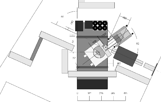
Figure 2.7: Beam area (![]() ) layout for Panofsky Ratio measurement. The 116 MeV/c
) layout for Panofsky Ratio measurement. The 116 MeV/c
![]() beam comes from the right of the figure, and stops in the liquid hydrogen
target (shown as the small circular object in the figure). The CsI (larger circular
object) and NaI arrays are shown to be positioned 180
beam comes from the right of the figure, and stops in the liquid hydrogen
target (shown as the small circular object in the figure). The CsI (larger circular
object) and NaI arrays are shown to be positioned 180![]() apart, out of the path
of the beam.
apart, out of the path
of the beam.
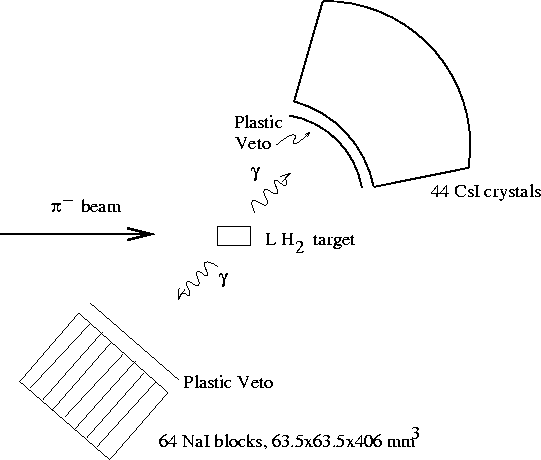
With this experimental layout, it is possible to detect the nearly anti-collinear
photons from the reaction ![]() , as shown in
Fig. 2.8.
, as shown in
Fig. 2.8.

Figure 2.8: Experimental layout for the Panofsky Ratio measurement, showing
the detection of the two nearly anti-collinear photons from the reaction
![]()
This detection requires a ``two arm trigger'' (See Sec. 2.2.5).