The CsI array is a subset of the final 240-element CsI spherical detector, as noted in
Sec. 2.2.1. In order to define the trigger for the 240-element detector,
the sphere has been divided into sixty overlapping clusters of CsI crystals. These
clusters are then divided into ten superclusters. The size of the clusters and
superclusters have been designed for optimum trigger efficiency, noise suppression, and
event pile-up rejection in the detection of ![]() 70 MeV photons from the pion beta
decay
70 MeV photons from the pion beta
decay ![]() [10].
[10].
As a subset of the final spherical detector, the 44-element array contains representative crystals from ten of the clusters and three of the superclusters. The array is triggered when the sum of the analogue to digitial converter (ADC) values from one cluster exceeds a threshold of approximately 5 MeV. Specifically, the CsI trigger is equal to the logical OR of the three superclusters, which is equivalent to the logical OR of the ten clusters.
Like the CsI array, the NaI array is divided into subsections of detectors in order
to define the trigger. In the 8![]() 8 array, there are 36 `inner' crystals, and
28 `outer' crystals. The NaI array is triggered when the sum of the ADC values of
the inner detectors exceeds a discrimator threshold equivalent to approximately 50 MeV,
and the sum of the ADC values of the outer detectors is less than another
threshold of approximately 15 MeV.
8 array, there are 36 `inner' crystals, and
28 `outer' crystals. The NaI array is triggered when the sum of the ADC values of
the inner detectors exceeds a discrimator threshold equivalent to approximately 50 MeV,
and the sum of the ADC values of the outer detectors is less than another
threshold of approximately 15 MeV.
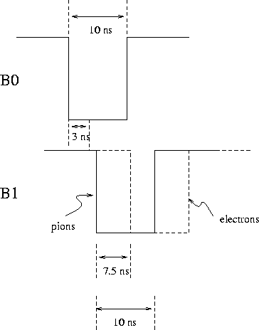
Another component to the event triggers is the coincidence between the beam
counters B0 and B1. This coincidence is included in the event trigger to ensure
the presence of a beam particle, and to select the correct type of beam particle.
For the 116 MeV/c ![]() beam, there is an electron contamination of a few percent.
Due to the thickness of the B1 counter, one can discriminate between
pions and electrons by their time of flight. Figure 2.9 shows a
reconstruction of the coincident signals from B0 and B1, with the timing set to
exclude electrons from the trigger.
beam, there is an electron contamination of a few percent.
Due to the thickness of the B1 counter, one can discriminate between
pions and electrons by their time of flight. Figure 2.9 shows a
reconstruction of the coincident signals from B0 and B1, with the timing set to
exclude electrons from the trigger.

Figure 2.9: Logic pulses forming the coincidence between beam counters `B0' and `B1'.
The beam electrons are excluded from the coincidence by their time of
flight.