The optical properties of six of the Bicron BC-400 thin plastic staves which
make up the twenty-element PIBETA cylindrical veto hodoscope have been
characterized using the CMT apparatus. These measurements were
difficult to make, due to several factors. First, two of the six multi wire
drift chambers in the CMT apparatus experienced an electrical short
somewhere inside the enclosed gas chambers. Thus, because extensive repairs
to the wire chambers
were needed, the measurements were halted with the limited number of
cosmic muon events which had been collected prior to this. Secondly, the plastic
staves are 60 cm long, which limits the uniformity of the cosmic muon event
acceptance. Specifically, the active area of the CMT apparatus is
60![]() 60 cm
60 cm![]() , but is not uniform over this region. As a result, the ends
of the plastic staves appear to be less illuminated than the middle, which affects
the extraction of quantities such as attenuation length and index of refraction.
The geometry specifications of one plastic veto stave are depicted in
Figure 3.12.
, but is not uniform over this region. As a result, the ends
of the plastic staves appear to be less illuminated than the middle, which affects
the extraction of quantities such as attenuation length and index of refraction.
The geometry specifications of one plastic veto stave are depicted in
Figure 3.12.
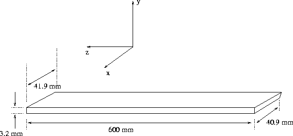
Figure 3.10: Geometry of plastic veto stave. Not shown are
the light guides and photomultipliers at each end.
In order to measure the scintillator light output nonuniformities and attenuation lengths, the staves have been coupled to light guides and arranged in the tomography box as follows:
As a first check in the analysis, one can plot the reconstructed entry and exit points of the cosmic muons intersecting the staves, extracted from wire chamber information. The results serve to check the reconstructed geometry and orientation of the set-up. Figure 3.13 shows the extracted entry and exit points for one stave, in the x-y, x-z, and y-z planes.
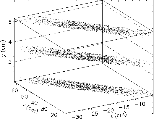
Figure 3.11: Reconstructed coordinates of cosmic muon hits
in plastic veto stave.
The axial light output per unit pathlength can be plotted for each end of the stave, using the appropriate ADC channel value divided by the calculated pathlength. A typical plot of the light output per unit pathlength against the axial direction is shown in Figure 3.14, measured from both ends of the stave.
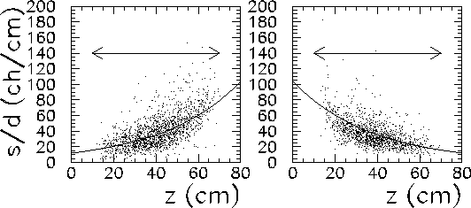
Figure 3.14: Light output per unit pathlength as a function of axial direction
for plastic veto stave, measured from both ends of the stave. The arrows
represent the length of the actual stave.
By fitting the scatter plot with an exponential function of the form
![]() , where
, where ![]() and C are constants, one
can determine the 1/e attenuation length
and C are constants, one
can determine the 1/e attenuation length ![]() . The fit was done
using the ``maximum likelihood'' method described in
Section 3.3.1. The measured attenuation lengths
have been tabulated for the six studied staves in table 3.2.
A conceptual diagram of the light attenuation along the stave is shown in
Figure 3.15
. The fit was done
using the ``maximum likelihood'' method described in
Section 3.3.1. The measured attenuation lengths
have been tabulated for the six studied staves in table 3.2.
A conceptual diagram of the light attenuation along the stave is shown in
Figure 3.15

Figure 3.13: Light attenuation along the length of a plastic veto
stave.
The transverse light output per unit pathlength is plotted in Figure 3.16, measured from both ends of the stave. The plots have been fit with a straight line, the slope of which can be used to calculate the transverse nonuniformity in percent per centimeter. The results are reported in table 3.2.
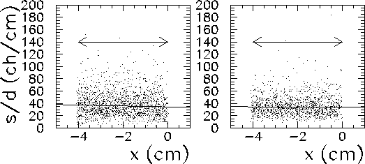
Figure 3.16: Light output per unit pathlength plotted against the transverse
direction for one plastic veto stave.
In order to view the light output per unit pathlength without the
attenuation, it is useful to plot the `geometric mean' M of the two
ADC values from each end of the stave. This quantity is defined
as
![]()
and is independent of position. The geometric mean in the
axial direction is plotted in Figure 3.17.
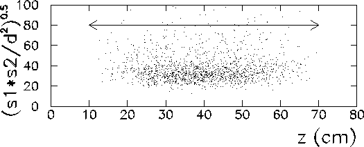
Figure 3.17: Geometric mean of the light output per unit pathlength
for one stave, in the axial direction. The arrow represents the
length of the stave.
From the figure, one can confirm that the geometric mean of the ADC values from each end of the stave is constant with respect to position.
The light output per unit pathlength can also be reconstructed in two dimensions. A typical example is shown in Figure 3.18, which depicts the light output per unit pathlength in both the axial and transverse directions, from each end of the stave.
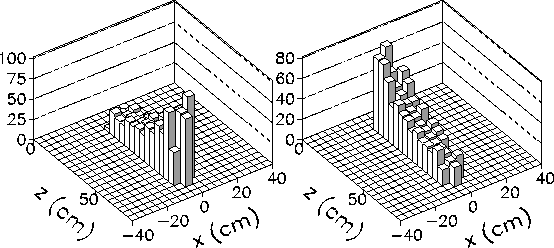
Figure 3.16: Reconstructed two-dimensional of light output
per unit pathlength for plastic veto stave. Each histogram represents the
output read by one photomultiplier tube at the end of the
stave.
As a check in the tomography measurements, it is useful to calculate the
index of refraction for each stave. This can be done by graphing
ln![]() against
against ![]() , where
, where ![]() and
and ![]() are the ADC values at each
end of the stave, and
are the ADC values at each
end of the stave, and ![]() and
and ![]() are the TDC values for
each end of the stave. Figure 3.19 shows such a plot,
with the straight line fit used to determine the slope. This fit was also
done with the maximum likelihood method.
are the TDC values for
each end of the stave. Figure 3.19 shows such a plot,
with the straight line fit used to determine the slope. This fit was also
done with the maximum likelihood method.
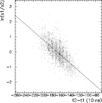
Figure 3.17: Graph of the log of the ratio of the two ADC values
from each end of one plastic veto stave, plotted against the difference
in TDC values for each end of the stave. The slope of the straight
line fit to this graph is used to determine the index of refraction
of the stave.
From Figure 3.15, ![]() and
and ![]() have
the values
have
the values

If the velocity of light in the stave is v, then ![]() , and
, and
![]() . Consequently, the slope of a graph of ln
. Consequently, the slope of a graph of ln![]() plotted against
plotted against ![]() is equal to
is equal to ![]() . By measuring this
slope m, one can calculate the effective index of refraction n in the
following way:
. By measuring this
slope m, one can calculate the effective index of refraction n in the
following way:
![]()

Table 3.2: Tomography results for six studied plastic veto
staves.
Table 3.2 lists the results of the plastic veto stave
tomography. The error bars are quite large in some cases. As explained above,
the cosmic muon statistics were limited by a malfunction in the multi wire drift
chambers. Another contribution to the uncertainty was the nonuniform acceptance
of the CMT apparatus over its active area. This led to difficulty in
determining the attenuation lengths accurately from a fit to the data.
The expected
attenuation length for the Bicron BC-400 plastic
scintillator material is 160 cm. [3]. However, this specification
has been measured for a 1![]() 20
20![]() 200 cm cast sheet of the
plastic scintillator material. This difference in geometry from that of
the PIBETA plastic veto hodoscope staves accounts for the tendency toward a
discrepancy between the measured values in table 3.2, and the
manufacturer's specifications.
200 cm cast sheet of the
plastic scintillator material. This difference in geometry from that of
the PIBETA plastic veto hodoscope staves accounts for the tendency toward a
discrepancy between the measured values in table 3.2, and the
manufacturer's specifications.
The expected value for the index of refraction n of the plastic stave material is 1.5. From the table it is clear that the measured values for n tend to be higher than this value. This is an expected result, due to the increased pathlength travelled by light undergoing many total internal reflections along the length of the stave. The TDC values for the light output depend on the discrimator levels, as only a small fraction of light travels straight down the length of the stave to stop the TDC early. The majority of the emitted light is reflected multiple times in the stave before reaching the PMT, which results in a larger TDC value and a larger value for n.