In order to evaluate the Panofsky Ratio, defined in Chapter 1,
the measured energy spectrum has been compared with the
simulation obtained from the GEANT Monte Carlo simulation [7]. By
varying the value of the Panofksy Ratio entered into the simulation code, and optimizing
the agreement with the data in terms of a minimum ![]() , one can deduce the most
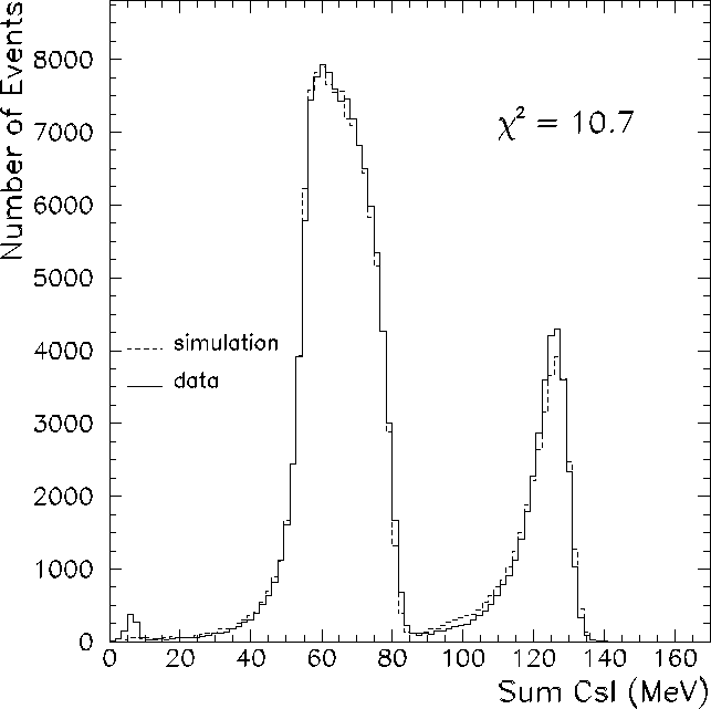
likely value for the Panofsky Ratio. Figure 7.11 shows an overlay of the
experimental histogram and the simulated spectrum, both with the requirement that less
than 4% of the total energy be deposited outside the central six crystals, for a Panofsky
Ratio value of 1.5 .
, one can deduce the most
likely value for the Panofsky Ratio. Figure 7.11 shows an overlay of the
experimental histogram and the simulated spectrum, both with the requirement that less
than 4% of the total energy be deposited outside the central six crystals, for a Panofsky
Ratio value of 1.5 .

Figure 7.11: Data (solid line) and simulation (dotted line) for the single arm trigger
configuration. The Panofsky Ratio value used in the simulation is 1.49, with less than
4% of the total energy deposited outside the central six crystals. The ![]() value
is calculated for events which deposit more than 20 MeV into the calorimeter. Charged
particle events are vetoed by the plastic hodoscope. The low energy feature represents
residual neutrons which were not removed with the B0 TDC timing cut.
Download ascii file.
value
is calculated for events which deposit more than 20 MeV into the calorimeter. Charged
particle events are vetoed by the plastic hodoscope. The low energy feature represents
residual neutrons which were not removed with the B0 TDC timing cut.
Download ascii file.
In order to optimize the agreement between data and simulation, the total ![]() value is calculated as
value is calculated as

where ![]() is the number of events in bin i of the simulated spectrum,
is the number of events in bin i of the simulated spectrum, ![]() is the number of events in bin i of the data spectrum,
is the number of events in bin i of the data spectrum, ![]() is the total number of
events in the simulated spectrum, and
is the total number of
events in the simulated spectrum, and ![]() that of the data spectrum. The standard
deviation
that of the data spectrum. The standard
deviation ![]() is taken to be the uncertainty of the data and simulation,
combined in quadrature, such that
is taken to be the uncertainty of the data and simulation,
combined in quadrature, such that

Defined in this way, the ![]() sum of the differences between experiment and simulation
is minimized with respect to the simulated Panofsky Ratio. The ``reduced
sum of the differences between experiment and simulation
is minimized with respect to the simulated Panofsky Ratio. The ``reduced ![]() '' value
is obtained by dividing the total
'' value
is obtained by dividing the total ![]() value by the number of degrees of freedom, which
is equal to the number of bins in the histogram minus the number of variable parameters
(one).
A graph of the reduced
value by the number of degrees of freedom, which
is equal to the number of bins in the histogram minus the number of variable parameters
(one).
A graph of the reduced ![]() value
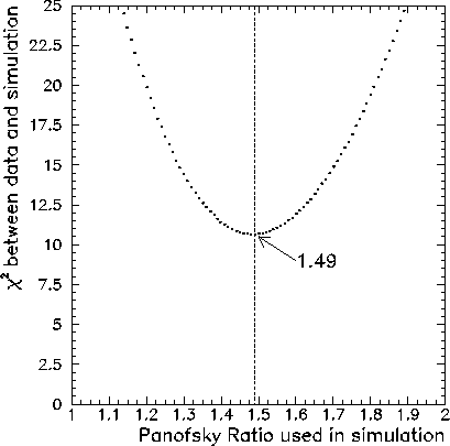
plotted against the Panofsky Ratio is shown in Fig. 7.12. From the graph, the
value of
value
plotted against the Panofsky Ratio is shown in Fig. 7.12. From the graph, the
value of ![]() is a minimum for a Panofsky Ratio of 1.49 . The uncertainty is
taken to be the change in the Panofsky Ratio for a unit increase in the value of
is a minimum for a Panofsky Ratio of 1.49 . The uncertainty is
taken to be the change in the Panofsky Ratio for a unit increase in the value of
![]() .
.

Figure: ![]() between the data and simulation plotted against the
Panofsky Ratio value used in the GEANT simulation. The total
between the data and simulation plotted against the
Panofsky Ratio value used in the GEANT simulation. The total ![]() value
is calculated according to Equ. 7.2.3.
The analysis was performed for a
minimum energy deposition of 20 MeV into the calorimeter (
value
is calculated according to Equ. 7.2.3.
The analysis was performed for a
minimum energy deposition of 20 MeV into the calorimeter (![]() =20 MeV), with less
than 4% of the total energy deposited outside of the central six
detectors.
=20 MeV), with less
than 4% of the total energy deposited outside of the central six
detectors.
As discussed in Sec. 7.2.2, several of the outer detectors exhibit a large
amount of low energy noise. Because the amount of this noise varies with the total energy
deposited into the calorimeter, the Panofsky Ratio evaluation can be sensitive to the level
of the veto energy threshold ![]() placed on the detectors outside of the central six.
Consequently, the
summing threshold
placed on the detectors outside of the central six.
Consequently, the
summing threshold ![]() defined in Sec. 4.1 has been raised to 1 MeV.
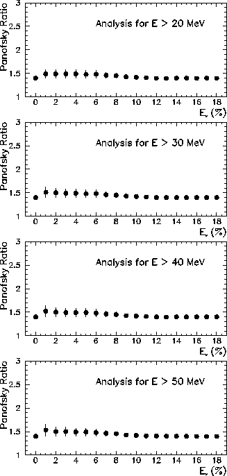
Figure 7.13
shows the extracted value of the Panofsky Ratio plotted against
defined in Sec. 4.1 has been raised to 1 MeV.
Figure 7.13
shows the extracted value of the Panofsky Ratio plotted against ![]() . From the
graph, one can see that the Panofsky Ratio is constant with respect to
. From the
graph, one can see that the Panofsky Ratio is constant with respect to ![]() ,
for
,
for ![]() .
.
As mentioned in Sec. 7.2.1, the Panofsky Ratio should be evaluated above
the energy threshold ![]() to avoid including events with significantly slewed timing
in the analysis. This threshold should be varied to verify that the results
are not sensitive to its value. Figure 7.13 shows the results for the analysis,
done with four different values of
to avoid including events with significantly slewed timing
in the analysis. This threshold should be varied to verify that the results
are not sensitive to its value. Figure 7.13 shows the results for the analysis,
done with four different values of ![]() ranging from 20 MeV to 50 MeV. The extracted
value of the Panofsky Ratio in the region where more than 92% of the total energy is
deposited in the central six crystals is 1.49
ranging from 20 MeV to 50 MeV. The extracted
value of the Panofsky Ratio in the region where more than 92% of the total energy is
deposited in the central six crystals is 1.49![]() 0.1.
0.1.

Figure 7.13: The extracted Panofsky Ratio values plotted against the energy
veto level ![]() for crystals outside of the central six, evaluated for energies greater
than four different values of the low energy threshold
for crystals outside of the central six, evaluated for energies greater
than four different values of the low energy threshold ![]() .
.
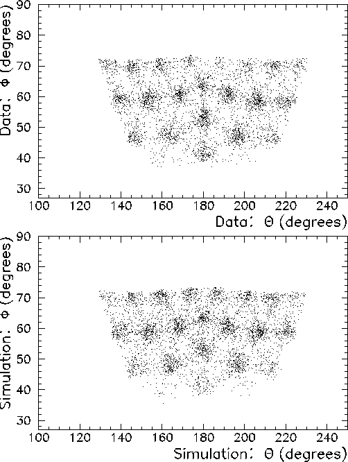
As a final check in the analysis, it is useful to plot the reconstructed shower origin coordinates for the one arm trigger configuration in the data and in the simulation. With identical cuts imposed, the spatial reconstruction of the shower origins in the data and simulation should show good agreement. Figure 7.14 shows that agreement.

Figure 7.14: Shower origin coordinates for the single arm trigger configuration.
Charged particle events are vetoed by the plastic hodoscope. The top scatter plot
represents the experimental data, and the bottom panel represents the
simulation.