


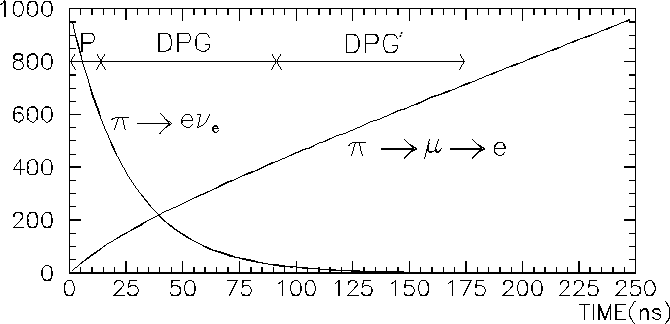
Three trigger gates are used for the experiment. Those are the Pion stop gate (P), Delayed Pion Gate (DPG) and DPG'. They are generated using beam counters, degrader and target. The target signal indicates a stopped pion that fires two beam counters. Immediately P is opened for ten nanoseconds, after this DPG is enabled for 80 ns. DPG is followed by DPG' which opens for another 80 ns.
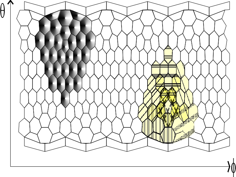
For the detection of a p b event a coincidence of two showers exceeding 55 MeV (the high threshold above the Michel endpoint) in two opposing sectors of the calorimeter is required. In order to generate a fast calorimeter trigger several crystals are combined into clusters. 220 calorimeter modules (without the veto crystals) are located in groups of six to nine crystals. So they are forming 60 overlapping clusters with the outcome that every vertex is contained in at least one cluster. Its applicability has been tested in Geant simulation and works due the fact that in most of the cases a large fraction of energy is contained in a single crystal or around a crystal vertex [Ass95].
The crystals in a cluster are summed using 12 analog adding modules (UVA 125), which have been designed at the University of Virginia. They provide two logical outputs for a high and a low discriminator threshold. Then using LeCroy 4518 Fan In/Out 10 so-called superclusters (SC) are formed by combining the 6 neighbouring clusters that surround the Pentagonal[11] crystals. This is done separately for the low threshold and the high threshold branch. The low threshold branch (SC Lo) will determine the calorimeter's timing, while the high threshold branch (SC Hi) contains the energy information above the Michel endpoint.
A SC Hi signal must be followed within 20 ns by another SC Hi signal from a non-neighboured supercluster during a valid DPG to record a p b event. For a p +->e+ n e event one shower exceeding 55 MeV during the DPG is sufficient. The DPG' mainly applies to the Michel decay due to the longer lifetime of a muon with 2.2 µs. The main processes and background decays are summarized in Table 3.
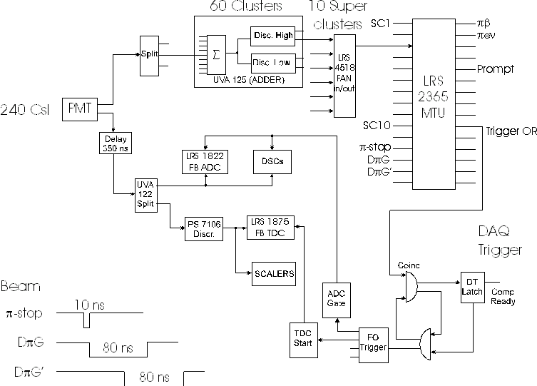
The inputs from P, DPG, DPG' and 10 SC Hi are generating the desired triggers
that are stored in pattern registers. So the
p +->e+ n e trigger, for example, is
formed by
 .)
The logical OR of various event triggers creates a LAM (`Look At Me') signal
and supplies the ADC gate as well as the TDC start signal. ADC and TDC analog
signals of all connected channels are FASTBUS modules (LeCroy 1822 and 1875)
while the logical modules are controlled through CAMAC interface. The master
trigger unit (MTU LeCroy 2365) is read by the data acquisition computer using
the PSI CAMAC Input/Output controlling unit IO506.
.)
The logical OR of various event triggers creates a LAM (`Look At Me') signal
and supplies the ADC gate as well as the TDC start signal. ADC and TDC analog
signals of all connected channels are FASTBUS modules (LeCroy 1822 and 1875)
while the logical modules are controlled through CAMAC interface. The master
trigger unit (MTU LeCroy 2365) is read by the data acquisition computer using
the PSI CAMAC Input/Output controlling unit IO506.
The data acquisition system used in the experiment is the called MIDAS [Rit97]. It provides a platform-independent data acquisition and controlling based on plain C++ code. MIDAS handles all of the on-line analysis, including the digital settings of threshold and delays, slow control (high voltage settings for the PMTs and temperature control for example) data readout and storing on mass storage devices. The same system provides the tools for off-line analysis, since it can be used with the PAW [PAW96] analysis tool including the generation of user specified n-tuples.
The actual values of all detector channels are read when the MTU signalizes the desired trigger pattern. Data in binary format can be stored simultaneously on tape and harddisk. Further information for an ongoing run such as time, temperatures, applied PMT high voltages, pedestal values, thresholds, etc. are stored in a database. The database entries are recorded at the beginning and the end of each run in the data file. Due to the low decay rate all background processes must be well under control. The background mainly comes from the p ->µ->e decay chain resulting in positron energies of mµ/2 at maximum - known as Michel positrons. Thus, a clear discrimination from p b - and p +->e+ n e-events is possible. A high energy threshold in the UVA 125 adder of 55 MeV will take care of most of it. The low threshold branch is dedicated for background studies and appropriately prescaled.
An important source of background for the p b signal are 4-fold accidental coincidences of Michel-events and p +->e+ n e g , since both are capable to exceed the high threshold level of 55 MeV. A highly efficient charged particle tracking is capable to identify this type of Michel background. The positron identification is done with the MWPCs which resolves double tracks. The hodoscope, on the other hand, can suppress the background from radiative decays by a cut on neutral particles (see Figure 2-3).
The p +->e+ n e trigger is more susceptible to be accidental background, since the presence of only a single shower within DPG is required. Besides cuts in off-line analysis a background pile-up rejection will be applied. With the fast digitization of all CsI pulses accidental coincidences can be suppressed. The applicability of this so-called `domino sampling chip' has been successfully tested [Bro96].
An additional source of background appears due to interaction of beam pions with target and degrader material resulting in hadronic particles. Neutral, as well as charged ejectiles, are suppressed by vetoing on the prompt gate. This also applies for single charge exchange (SCX) in the degrader which would result into a p 0 background at 6*10-6 level. A 10 ns delay of the PG can rule out entirely the p 0 emanating from SCX in the degrader. This was demonstrated in the 1994 beamtime [Ass95,Bro96].
The thermal-house will be surrounded with 5 cm thick lead bricks to inhibit ambient background to enter the calorimeter. In order to reject cosmic muon initiated showers - besides a clean pion stop trigger- large plastic scintillator paddles roofs the lead-house. The logical OR of the paddles will also be fed into the master trigger in order to act as a veto. The lead house is needed to prevent self vetoing by particles escaping the calorimeter, such as soft photons, electrons or positrons. In addition the suppression of ambient background, mostly neutron induced reactions inside the experimental area, is valuable.