

3.3.4 Detector components used in the 1996 and 1997 beam times
The 1996 and 1997 pibeta beam times incorporated similar detector and beamline
components. The two most significant changes from 1996 were:
* The replacement of four "dummy" crystals with real ones
* The removal of a large dipole magnet from the p E area (discussed in
section 3.2.2)
The following is a list of detector components used in the 1997 beam time.
Each is discussed below.
* Platform
* Beam counter and collimator
* Multi-wire proportional chambers
* Thermal house
* Degrader and target
* Plastic veto array
* CsI crystal array
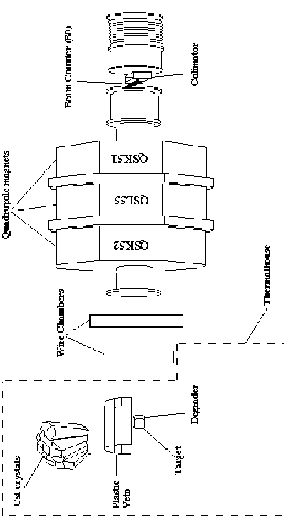
Figure 3.10 shows a diagram of how most of these components were positioned
during the 1997 beam time.
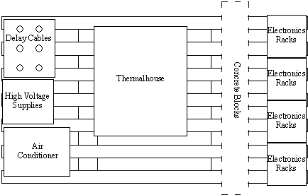
Most of the apparatus was mounted on a base structure made of steel girders.
Figure 3.11 shows an overhead view of this structure indicating the placement
of the attached elements. Mounting much of the experimental apparatus rigidly
on this structure made it possible to connect many of the wires and to position
many of the detector components prior to gaining access to the p E1 area. The
structure contained the

Figure 3.10: Arrangement of the detector elements used in the 1997 beam
time.

Figure 3.11: The 1996 and 1997 experimental apparatus. Elements are
supported by a structure of steel girders from underneath. Cables were run from
the detectors inside the thermal house under the concrete blocks and between
girders to the electronics racks.
electronics racks, thermal house and swing, delay cables, air conditioner, and
high voltage power supplies. It weighed over 5 metric tons, and was moved into
the area using a large crane which spanned the experimental hall. Large
concrete blocks were then placed on the girders between the electronics racks
and the detectors so as to provide shielded access to the electronics while the
beam was on.
Just after entering the p E1 area, the particle beam was collimated using a
lead brick with a 1.5 cm diameter hole in it in the beam direction. Just on the
downstream side of the collimator was a 1mm thick plastic scintillator
detector. This was called B0 and was used for detecting beam
particles as they entered the p E1 area.
Two multi-wire proportional chambers were positioned between a triplet of
quadrupole magnets (QSK51,QSL55, and QSK52) and the thermal house. Unlike the
MWPCs built for the pion beta decay detector, the chambers used in 1996/1997
were flat and square. Each of the MWPCs contained both an X and a Y plane. All
planes had a wire spacing of 1mm. The MWPCs were read out using a LeCroy
Research Systems (LRS) PCOS III system, the same system that will be used to
read out the cylindrical MWPCs to be used in the full pion beta decay detector.
The two MWPCs were placed with their centers 507 mm apart and normal to the
beam. These were useful only for beam profiling.
The thermal house (TH) was constructed out of wood and dense, thick Styrofoam.
The shelter completely enclosed the swing, CsI crystals, plastic veto, and
target/degrader package. The TH served to provide a temperature and humidity
regulated environment for the CsI crystals improving their behavior and
stability. Using heaters inside the TH, a control system was able to keep the
temperature there stable (±1° C) at a few degrees above 0° C.
The temperature regulator was designed and built at the University of Virginia
and incorporated circuits that would switch on and off the heaters as the 50 Hz
AC passed through zero volts. This helped to reduce the amount of noise
introduced into the signal electronics by the heaters switching on and off. The
TH sat on a large, rotating platform such that the focal point of the CsI
crystals was on the axis of rotation. The TH and all its contents could thus be
rotated >30 degrees to either beam left or beam right. Markings on the
rotation mechanism allowed the angle at which the TH was positioned (relative
to the beam) to be read easily and accurately.
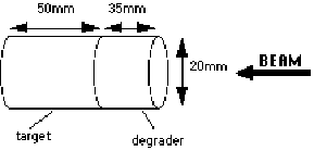
Two cylindrical plastic scintillator detectors were used to stop pions in the
beam near the focal point of the CsI array allowing them to decay in the rest
frame of the lab. A diagram of these pieces is shown in Figure 3.12. The
upstream detector (called D0 )was 35 mm long with a radius of 20 mm and
was used to slow the pions such that they would stop at the center of the
target. The downstream detector, called T0, was 50 mm long with a radius of 20
mm and was the target in which the pions were stopped. The D0 and
T0 detectors were individually optically coupled to small,
surface-mounted Hamamatsu photosensors and sealed from light leaks. They were
mounted on a stand at the focal point of the CsI array.

Figure 3.12: Target and degrader. The pions, entering from the right, are
slowed by the degrader so as to stop near the center of the target.
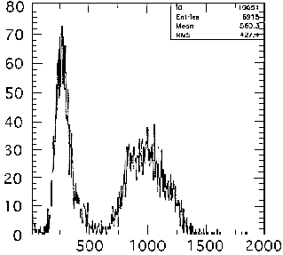
The main uses of the plastic veto are (1) to distinguish between the lighter,
minimum ionizing particles (positrons and electrons) and the heavier charged
particles (pions and muons) going from the target to the CsI calorimeter, and
(2) to distinguish between different particle types as illustrated in Figure
3.13. For the 1996/1997 runs, the plastic veto array consisted of eight long,
thin scintillator staves positioned between the target and CsI crystals. The
pieces were arranged to form a partial cylinder whose center coincided with the
beam line. The preparation and properties of the PV detector is discussed in
detail in chapter 4. For the 1997 beam time, half-sized staves were used.
An array of 44 pure CsI crystals was used in the 1997 beam time. For the final
pion beta decay experiment, an array of 240 crystals will be used. The crystals
fit together so as to form a spherical shape which will cover nearly eighty
percent of 4 p as seen by a particle at the sphere's center. The sphere will
be open on two opposing sides for the beam entrance upstream and downstream for
access and wiring for the inner detectors.
Pure CsI was chosen because of its fast recovery time (the fast component of
the CsI pulse is on the order of 30 ns wide so the crystal can accept a high
rate of events without overlapping signals). This is needed to handle the high
rates necessary to collect the necessary statistics in a reasonable amount of
time (1 year of beam time). There are crystals of six different shapes: (a)
Pentagon, (b) HexA, (c) HexB, (d) HexC (e) HexD, (f) HexD2 and (g) Veto . The
pentagons are the only regularly shaped crystals. Due to the precision desired
for the pion beta decay experiment and the exceptionally small branching

Figure 3.13: Plot made from one of the plastic veto half-staves during the
1997 beam time. The narrow peak to the left is made from the minimum ionizing
positrons. The broad peak to the right is from heavier, slower moving particles
(e.g. pions being scattered elastically off a nucleus).
ratio for pion beta decay, a large degree of modularity was required for the
calorimeter. The final design was achieved by a geodesic breakdown of an
isocahedron [Ass 95].
The data acquisition system for the pibeta experiment has been designed using
fast electronics and custom acquisition software. A high data rate is critical
to make the experiment a success using the allotted beam time. Sophisticated
logic has been hardwired into the electronics as described in section
3.4.1. Section 3.4.2 discusses the data acquisition system designed
specifically for the pibeta experiment.


