

Next: Contaminations and Beam
Up: Beam Contaminations and
Previous: Beam Contaminations and
The first task for beam set-up is to set the magnet for the desired pion rate
while minimizing the muon and positron contaminations.

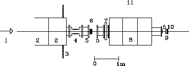
Figure: Beam line set-up for
optimization during the test run of 1992:  secondary beam (central trajectory);
 quadrupole magnets;
 concrete shielding for proton channel;
  vertical steering magnet;
 mylar windows,
  lead collimator(opening: 7 cm vertical, 2 cm
horizontal, thickness
  cm;
cm;  horizontal steering magnet;
  quadrupole triplet;
  multi-wire proportional chamber(MWPC);
 scintillator
  ,
, 
 area.
area.
At a given pion momentum,
the nominal magnet settings are used as the initial inputs of an
optimization algorithm. With these initial settings, the optimization
algorithm known as OPTIMA calculates the particle rate in a scintillator
counter placed at a waist.

Figure: Electronics diagram for beam
optimization and Time Of Flight analysis.
Then, for each unit in the beam channel except the momentum defining magnet,
OPTIMA varies the
corresponding setting within a given range with a given step size around the
initial value for a maximum rate in the scintillator.

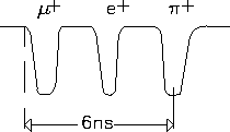
Figure: Time
separation observed on the oscilloscope between  ,
,  and
and  at 116 MeV/c.
The observed counting rate
in the scintillator is normalized to the proton rate during the counting period
to account for fluctuations in the primary proton current.

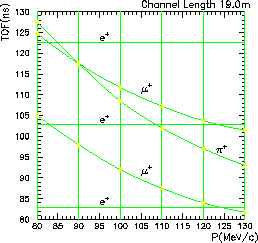
Figure: Time of
flight in the secondary beam line of  ,
,  and
and  at various momenta. For
the pion beta experiment, the central beam momentum is set at
  .
.
When all the magnets are set at their optimum values, OPTIMA calculates again the
rate in the scintillator and returns the ratio of the final rate to the
initial rate as the gain. An iterative process is then performed until the
gain is close to unity.

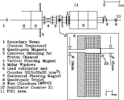
Figure: Beam line arrangement
for phase space studies during the 1993 test run.
The beam line set-up and the electronics diagram for optimization purposes
during the test run of 1992 is shown in figure  and
figure
  respectively. The MWPC monitors
the horizontal and vertical beam profiles at the waist.
A time of flight (TOF) analysis is conducted before and after the optimization
in order to determine the fractions of pions and the contaminating
particles (muons and positrons) in the beam.
The optimization scintillator provides the start signal for
the Time to Analog Converter while the stop signal is the suitably delayed RF signal,
which marks a particular phase of the accelerator frequency
(see table
  ).
The optimization branch of the electronics involves the selection of the
particle type ---
  in this case --- for which the magnets are to be
optimized using the coincidence,
  , in
figure
  . Triggering an oscilloscope with the scintillator and
looking at the RF, one observes at 116 MeV/c, a clean separation between
particle types as shown in figure
  .
This observation agrees well with the
expected separation displayed in figure
  . Once the selection is made,
the coincidence output is sent to a scaler whose counts are used by the optimization algorithm.


Next: Contaminations and Beam
Up: Beam Contaminations and
Previous: Beam Contaminations and
Bernward Krause
Mon Jan 15 14:57:06 MET 1996

 secondary beam (central trajectory);
 quadrupole magnets;
 concrete shielding for proton channel;
  vertical steering magnet;
 mylar windows,
  lead collimator(opening: 7 cm vertical, 2 cm
horizontal, thickness
  cm;
cm;  horizontal steering magnet;
  quadrupole triplet;
  multi-wire proportional chamber(MWPC);
 scintillator
  ,
, 
 area.
area.


 ,
,  and
and  at 116 MeV/c.
 ,
,  and
and  at various momenta. For
the pion beta experiment, the central beam momentum is set at
  .
.

 in this case --- for which the magnets are to be
optimized using the coincidence,
  , in
figure