Table:
 beam characteristics
(Full Width Half Maxima) as measured during the 1993 test run.


Following the optimization and TOF analysis, a system of two MWPC is set up along the beam to monitor the horizontal and vertical beam profiles and to determine the divergences.

Table:  beam characteristics
(Full Width Half Maxima) as measured during the 1993 test run.
The beam line set-up during the test run in 1993 is shown in figure  .
The position of the first wire chamber is the waist
where the beam spot size is expected to be minimal. If the hits in the
MWPC's shown in figure
  are
are  and
and  respectively, the
divergences are defined as follow:
and
where D is the distance between the two MWPC's.
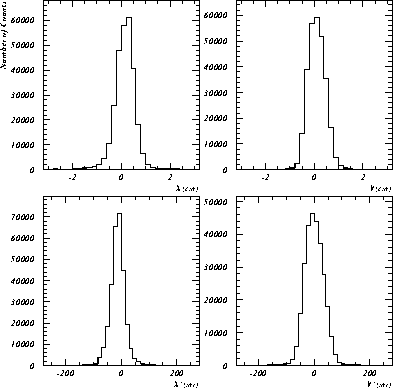
The horizontal and vertical characteristics of the beam during the
test run of 1993 are shown in figure  .
The Full Width Half Maxima (FWHM) of the beam profiles and the divergences
are presented in table
  .
.
The horizontal and vertical phase spaces  and
and  are shown
in figure
  .
.

Figure: Beam profiles and divergences
as measured during the 1993 test run.

Table: Beam particle rates and contaminations.
The average proton current during the run was  . The
. The  beam-momentum was
  , and the momentum spread was
  (FWHM).
A two-dimensional display of the of the energy deposited in the
scintillator (see figure  ) versus the timing of the RF signal
reveals the composition of the beam as can be seen in figure
  ,
and allows a quantitative determination of the particle rates.
The rates and contaminations based on these cuts are summarized
in table
  .
.

Figure: Horizontal and vertical phase spaces  and
and  at the waist.

Figure: Beam spot at the waist. With a diameter less than
one centimeter, the measured beam spot satisfies the requirement for the pion beta
experiment.

Figure: Scintillator ADC versus RF timing (TDC).
The muon regions to the left, the positron regions below the muon band but slightly
to the left and the pion regions to the right are clearly visible. By making cuts on
the regions, the rates of the beam particles at the scintillator can be
determined.


