 .
.


The pion beta calorimeter is produced with a class II type of breakdown and
frequency 10.
In the class II breakdown, the triangle that is drawn and
subdivided is not a polyhedron face. Rather, the class II triangle straddles
the common edge of two polyhedron faces and its base joins their centroid as
displayed in figure  .
.

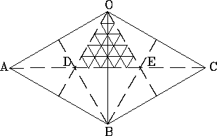
Figure: An example of a class II breakdown. The
class II triangle is not an icosahedron face. The class II triangle ODE straddles the
common edge OB of the two polyhedron faces OAB and OBC. For a 10-frequency breakdown,
one makes a 5-frequency breakdown of the class II triangle which, on reflection DEB,
produces the full 10-frequency breakdown.
There are 60 such triangles clustered five to an icosahedron vertex. The class II triangles are what the class II breakdown actually subdivides. For an f-frequency breakdown, one makes an f/2 subdivisions of the class II triangle which, on reflection, produces an f divisions of the common edge, i.e. an f-frequency subdivision.
The coordinates of the vertices are obtained as follows: each vertex is
assigned three numbers  whose sum is always the frequency of
the breakdown as shown in figure
  .
The coordinates in the local
reference frame are given as [Ken-76]


Figure: The convention for producing the coordinates of
the vertices. The class II triangle is subdivided according to the breakdown frequency f,
(f=10 in the case of the pion beta calorimeter). Then the vertices are
numbered in an orderly fashion to obtain the first digit  . A
. A  clockwise rotation gives the second integer
  . Another
  rotation results in the third digit
  . At each vertex
  .
In (d), by removing some lines of the grid, the pattern of the calorimeter
modules emerges.
The coordinates in the world reference frame are given by two rotations. The
first one around the z-axis by an angle  followed by a rotation
around the new y-axis by
  .
.  and
and  are
inherent to the geometry of the icosahedron. For one hemisphere,
 while
while  with the special case
  and
and  . The reflection

gives the other hemisphere which is rotated with respect to the previous one
by  . From the center of each pentagon, start portions of five
great circles. At
  of the
  circuit,
each great circle runs into the center of another pentagon. At the center of a
pentagon, five triangles of the icosahedon meet.
 is the
angle between the line going through the center of a pentagon and the plane of
one of the triangles which meet at that center. The angles
  follow from
the fact that, at
  , the centers of five pentagons are
 apart.
From figure  , five consecutive rotations of
  will produce a complete pentagon, five hexagon A, five hexagon B and 5
hexagon C. At this point, one has only 10 halves of the hexagon D. The full
hexagon D are obtained from mirror symmetry at which point the total count of
modules comprises 2 pentagons, 10 hexagon A, 10 hexagon B, 10 hexagon C and
10 hexagon D. When the whole sphere is completed, one has 12 pentagons, 60
hexagon A, 60 hexagon B, 60 hexagon C and 60 hexagon D.

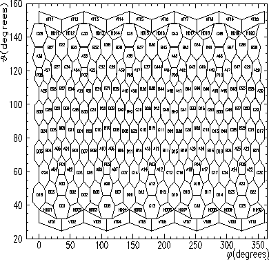
Figure: A 2-dimensional projection of the calorimeter showing
the relative positions of the modules. The different shapes are clearly
recognizable and the module names are also supplied. The pentagons for
instance are named P01 through P10 while the hexagon A's are A01 through A50
and so on. In the nomenclature of the HD's and the vetoes, the odd numbers
are the HD1, VT1 while the even number are the HD2 and VT2.
The breakdown algorithm is presented in appendix A.
The next step in the
design was to make openings for beam entry and readout of inner detectors and to
create the shower vetoes. As a result, the pentagon at
 and its mirror symmetry together with all the
modules associated with them were removed. This process leaves only 10
pentagons in the calorimeter, 50 hexagon A, 50 Hexagon B, 50 hexagon C and
40 full Hexagon D and 20 half hexagon D. The shower vetoes were designed as
one quarter of a hexagon C plus one half of a hexagon D. There are 20 such
veto elements bringing the total number of calorimeter modules to 240. At this
stage of the design,
there was no gap in the calorimeter to account for the
wrapping of the crystals. However, a gap of
  (between the
modules) was required. In addition, the vertices at the front
and back ``faces'' of the modules were all not in the same plane. These
problems were dealt with by solving the simultaneous equations describing the
intersection of three planes taking into account the gap and requiring that
the z-components of the vertices be same, i.e.
  at the front
face and
  at the back face of the modules. As a result,
the truncated pyramids described in the previous chapter were arrived at and
the information regarding their linear and angular dimensions were also
obtained for their fabrication. The positions of the modules relative to one
another are illustrated in figure 6.4. Also shown in the same figure is the
nomenclature which indicates the type and the position of any given module in
the calorimeter. The complete algorithm for producing the
coordinates of the modular vertices is described in appendix B.


