By assuming that the target is a point source, the angle of incidence of the particle can be calculated for each event. This approximation holds as long as the actual target size is small compared to the distance between the target and detector arrays.
For the NaI detector, the angle of incidence correction is calculated
along the two directions in the plane of the front face of the array,
![]() and
and ![]() . The technique used is similar to the one
suggested by A. Bay et. al. [1]. The shift
. The technique used is similar to the one
suggested by A. Bay et. al. [1]. The shift ![]() (or
(or ![]() ) is applied according to
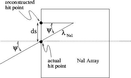
Fig. 5.2, where
) is applied according to
Fig. 5.2, where ![]() is related to the
electromagnetic shower penetration depth and is a function of energy.
From Fig. 5.2 one can see that
is related to the
electromagnetic shower penetration depth and is a function of energy.
From Fig. 5.2 one can see that
![]() .
.

Figure 5.2: Geometry used to calculate angle of incidence corrections
![]() to shower reconstruction coordinates in NaI array.
to shower reconstruction coordinates in NaI array.
For the CsI detector, which has a spherical geometry, the angular
correction ![]() is applied to produce a shift in the
is applied to produce a shift in the ![]() and
and
![]() directions, which are also along the front face of the array.
First, the angle of incidence
directions, which are also along the front face of the array.
First, the angle of incidence ![]() with the normal to the detector surface
is calculated in each direction
with the normal to the detector surface
is calculated in each direction ![]() and
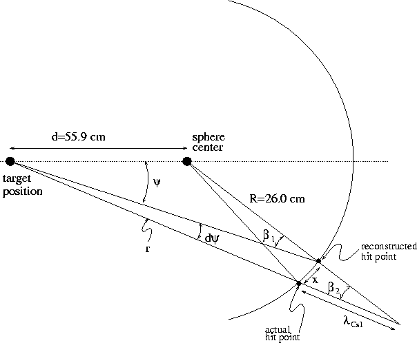
and ![]() , as shown in
Fig. 5.3.
Next, because the linear correction x is small compared to the distance
to the target r, one
can assume that
, as shown in
Fig. 5.3.
Next, because the linear correction x is small compared to the distance
to the target r, one
can assume that ![]() . Assuming that the linear
correction x is much less than the sphere radius R, one can see from
Fig. 5.3 that
. Assuming that the linear
correction x is much less than the sphere radius R, one can see from
Fig. 5.3 that
![]() .
Finally, the angular correction
.
Finally, the angular correction
![]() in both the
in both the ![]() and
and ![]() directions takes the form
directions takes the form
![]()

Figure 5.3: Geometry used to calculate the angle of incidence correction
![]() to the reconstructed shower coordinates in the CsI array.
to the reconstructed shower coordinates in the CsI array.
The values of the shower depth parameters ![]() and
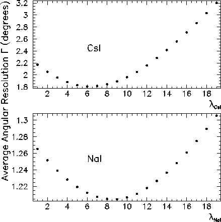
and ![]() have been chosen for optimal average angular resolution. Figure 5.4
shows the plots of average angular deviations
have been chosen for optimal average angular resolution. Figure 5.4
shows the plots of average angular deviations ![]() plotted
against
plotted
against ![]() ,
for 55-83 MeV photons from the reaction
,
for 55-83 MeV photons from the reaction ![]() in the GEANT
simulation. One can see that the
optimal values are
in the GEANT
simulation. One can see that the
optimal values are ![]() cm and
cm and ![]() cm. These penetration
depths reflect the fact that the NaI crystals have a lower atomic number than the
CsI crystals, shown in the larger value for
cm. These penetration
depths reflect the fact that the NaI crystals have a lower atomic number than the
CsI crystals, shown in the larger value for ![]() .
.

Figure 5.4: Average angular deviation plotted against the shower
penetration depth parameter ![]() , for the CsI array (top panel)
and NaI array (bottom panel).
, for the CsI array (top panel)
and NaI array (bottom panel).
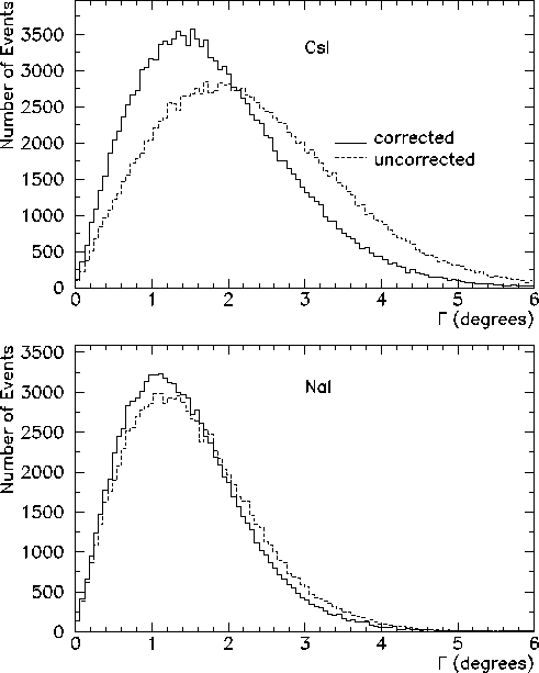
Finally, the event-by-event angular deviations ![]() are plotted in
Fig. 5.5, with and without the angle of incidence corrections.
It is clear that there is a significant improvement with the inclusion of
the correction. The CsI
are plotted in
Fig. 5.5, with and without the angle of incidence corrections.
It is clear that there is a significant improvement with the inclusion of
the correction. The CsI ![]() decreases from 2.3
decreases from 2.3![]() to
1.8
to
1.8![]() , and the NaI
, and the NaI ![]() from 1.3
from 1.3![]() to 1.2
to 1.2![]() .
.

Figure 5.5: Angular deviations ![]() , with and without the angle of
incidence corrections, for the CsI array (top panel) and NaI array
(bottom panel).
, with and without the angle of
incidence corrections, for the CsI array (top panel) and NaI array
(bottom panel).