


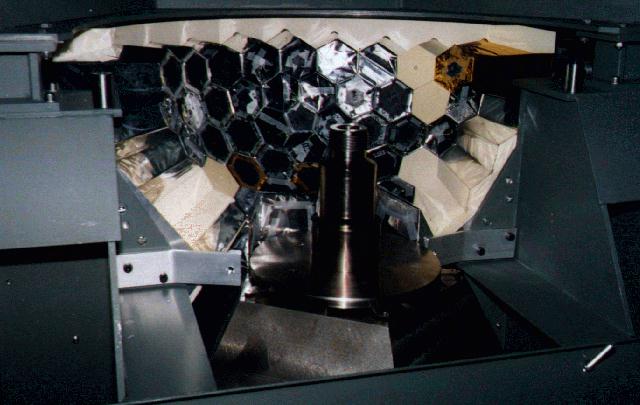
The CsI array with the swing was surrounded by a thermal house made of 4 cm thick styrofoam. In order to limit pion beam absorption the front shielding only consisted of two cardboard sheets of 300 µm thickness each.
In order to probe several parts of the CsI array it was mounted on a swing that was mobile in theta- and phi-direction. The pivot coincided with the centre of the sphere and with the reaction centre. The array had to be moved out of the central point for measurements involving the LH2-target to allow the mechanical support structure to fit in.
In order to veto against lateral shower losses, the NaI-wall was electronically subdivided in two parts. An array of the central 6x6 crystals formed NaIinner and a ring of the 28 outermost modules formed NaIouter.
The CsI calorimeter trigger scheme follows the description of superclusters in chapter 2. Groups of 6 to 9 crystals were generated and the correspondent analog signals from the PMT voltage divider were added using the UVA 125 summing modules. The 10 resulting clusters built the supercluster logic, which also was fed into the MTU. The so-called `high' threshold was set at about 2 MeV.
In order to build the NaI trigger, the linear sum for the NaIinner and NaIouter-branch was generated separately with the UVA 125 summing modules. A valid event required a signal from the NaIinner-Sum which was vetoed if NaIouter-Sum exceeded the chosen threshold. The trigger during the runs with the LH2 target was threefold to allow two tasks at the same time. A coincidence between B0,B1, NaI- and CsI-calorimeter (see Figure 6-3) was built to detect simultaneously the two photons from the p 0-decay in both calorimeters. In addition, the so-called `single-arm' trigger was generated. It required the presence of one photon in either detector and thus registered the two competitive p N reactions. This trigger mode was prescaled to allow a high counting rate for the coincidence mode. The main trigger consisted of a coincidence between the two beam counters and the two arms of the detector. In order to avoid RC events in the coincidence mode, the thresholds for both detectors were set well above 10 MeV. The coincidence between both detectors also was used for calibration, since the p 0-energy adds up to 137.86 MeV.
The selection of the trigger of interest for data analysis was available through the output pattern of the MTU which was stored along with the energy and timing information. Furthermore the temperature was monitored continuously at six positions within the CsI thermal house.