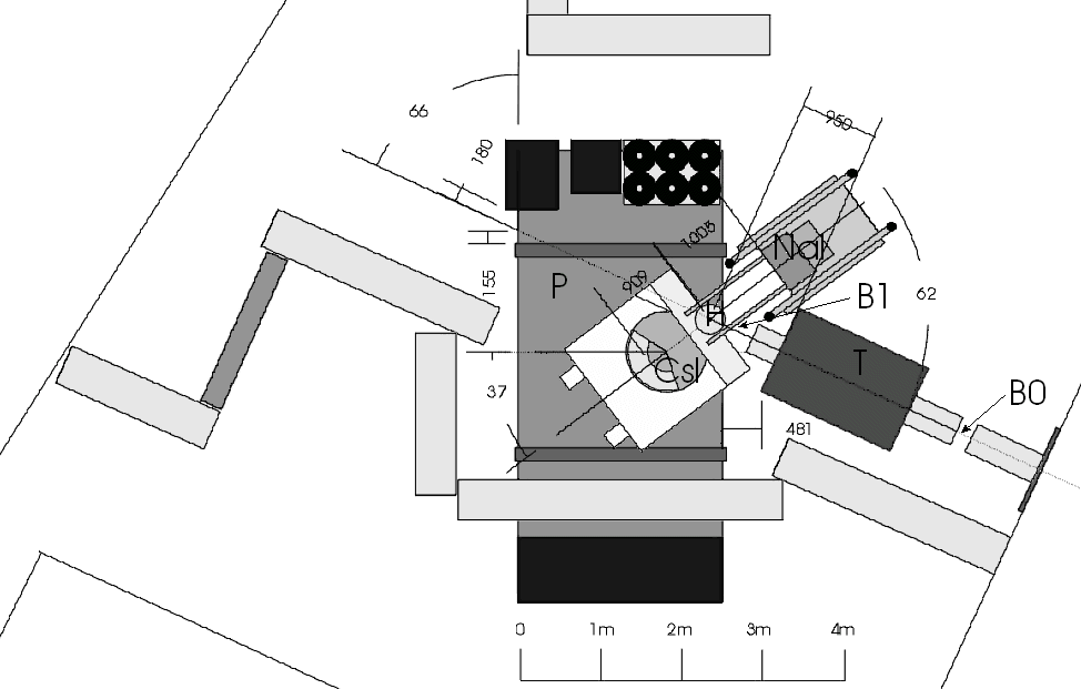


The negative pion beam was optimized for high rate and low contamination of leptons. As in the final set-up, also to be located in the p E1, a momentum of 116 MeV/c, was chosen (see chapter 2). In the first focus directly after the beam enters the area a 0.1 cm thick plastic scintillator was located to register beam particles. It was followed by a quadrupole triplet that imaged the focus onto the target. A second beam counter (B1) of 1 cm thickness was placed right in front of the LH2-target vacuum housing to provide timing information before the pions stop in the target. The combination of both counters was used for beam particle discrimination and as a veto detector for scattered particles and in-flight-decays. We achieved a p - stop rate in the target of 105 p -/s.
The target consisted of a LH2 vessel plus a surrounding vacuum cylinder. The target vessel was a 150 µm capton foil cylinder, 10 cm long and 4 cm in diameter. Liquid hydrogen was filled in the vessel through an iron pipe that entered the flange on which the capton vessel was mounted. In front of the vessel 2 cm of CH2 was inserted to degrade the pions such, that they entirely stopped within the liquid hydrogen. Another 6 mm of carbon was added as a degrader in front of B1. The optimal thickness for the degrader was obtained by checking the trigger rate using different degrader thicknesses. The stopping distribution of the pions in the target was modelled using a GEANT simulation of the target (section 7.5.1). The vacuum housing had a diameter of 120 mm and was made of 1 mm thick aluminium. It was enclosed in a 190 µm mylar foil to allow the presence of two windows facing the calorimeters. These windows minimized absorption, pair conversion and scattering of the photons.


