The Domino Sampling Chip in the PiBeta Experiment

The Domino Samping Chip was designed to sample the signal waveforms
from different detectors of the PiBeta Experiment. After develoment of
the full system we are taking data with the DSC for 240 CsI crystals
(module 0...4), 40 Plastic Veto counters (module 5) and 16 target and
beam counters (module 6).

General Description
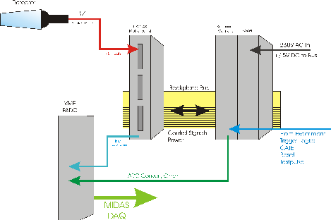
The DSC system consists of three components which are connected via a
backplane bus: The Power Module provides the DSC system
power. It gives out the necessary +/- 5V, -1.5V and +3.5V. The
DSC Controller or DSC Sequencer receives the control signals from the
experiment as GATE, RESET, START
Conversion and Testpulse.
It gives out the Flash ADC GATE and the Flash ADC
Converts as the DSC control signals /Busy,
Read Bit In (RBI), Clear, Enable
Zero Suppression (EnZS), the Readout Phase clocks Phi
1 and Phi 2, Gate and the
Testpulse.
The main part of the DSC Sequencer is an Altera epm7032s FPGA which
produces all control signals from the input signals.
The Controller and the necessary signals are described on theController Page
Details on the necessary control sequences you can find on the DSC Homepage.
Details on the Motherboard
Learn how it looks like and what the components are for.
Pictures and PS-Downloads

 Return to the DSC Main Page
.


H.P. Wirtz, last update 09-Aug-2000


