Properties of the 3" EMI 9822QKB PMTs


There are 240 CsI crystals in the calorimeter ball, of which 200 require
3" photomultiplier tubes (PMT). Our trigger efficiency and background
correction requirements place the following demands on PMT gain and
linearity:
- Linearity better than 2% over the full dynamic range of the
calorimeter.
- Gain stability better than 2% over time intervals shorter
than the mean time between gain measurements.

Discussion of PMT non-linearity
We have adopted a Bill Stephens modification of the EMI recommended high
voltage divider. This divider minimizes
the so-called "super" or "over"-linearity exhibited by many PMTs well
below the onset of saturation.
The figure below shows the high voltage
divider currrently used in our linearity tests described below.


 PostScript
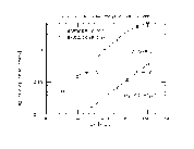
The next figure shows gain as a
function of voltage for two versions of the 9822 PMT.

 PostScript
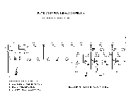
Below is shown the high rate FET base currently under production
for the pibeta experiment.

 PostScript

Discussion of PMT rate-dependent gain shifts
Ideally, the gain of a PMT is constant. In practice, the gain
depends on a number of external factors such as temperature and
magnetic field, as well as the average anode current arising from
the photon flux at the cathode. This latter effect can be
attributed to several causes:
- Changes in voltage distribution across the last few dynode stages
due to excessive average anode current (> 50 microamps) or peak pulse
current. This kind
of gain shift can be reduced by minimizing the ratio of anode current to
resistor string current and placing adequately sized capacitors on the
last few dynodes. Ultimately, space charge effects limit the gain of
any PMT.
- Changes in the dynode material secondary emission properties arising
from direct impact heating, and dynamic surface chemistry effects
such as ion migration. These effects depend on dynode composition and
occur at much smaller anode currents (1-10 microamps).
Our high voltage divider is designed to minimize contributions from the first
type of gain shift. To reduce the dynode dependent effect we have chosen
the SbCs dynode offered by EMI.

Estimate of Michel background rate
The following parameters define the problem:
- Pion stopping rate: 1E6 per second
- LeCroy 1882F 12 bit ADC full scale: 170 pC
- Maximum energy in ADC: 120 MeV
- Attenuation of PMT signal due to splitters: 1/8
- Average Michel energy: 45 MeV
- Solid angle of CsI crystal: 4pi/240
Thus, the resulting ADC sensitivity is 1.4 pC/MeV or 11 pC/MeV
at the PMT. The gain necessary to achieve this depends on the
photoelectron/MeV efficiency of each CsI crystal/PMT combination,
e.g- 150 p.e./MeV requires a gain of 6.8E5. In any case, there
will exist a Michel background of 4 kHz in each CsI crystal
with an average charge/pulse of 500 pC, or 2 microamps.

Test setup used to measure rate dependence of gain
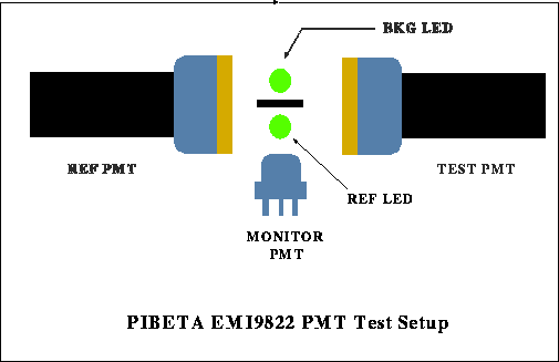
We use a two LED technique to measure the rate-induced gain shift. A reference LED,
shown in the diagram below, is pulsed at 10 Hz and the gain of the PMT
adjusted to produce a charge/pulse of 780 pC, corresponding to the charge
expected from a 70 MeV pibeta photon. A background LED is pulsed at a computer
adjustable rate from 25 Hz to 18000 Hz, with a charge/pulse approximately
1/2 of the reference LED. An ADC is used to digitize the PMT charge resulting
from the reference LED.
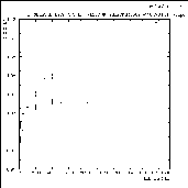
A comparison of the gain shift as a function of background LED rate for
BeCu and SbCs dynodes is shown below.

 PostScript
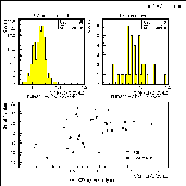
Finally the gain shift at 5 kHz has been measured for all pibeta 9822QKB
PMTs currently in house at UVa and PSI. A comparison of BeCu and SbCs
dynodes is shown below.

 PostScript

Database of UVA rate effect measurements:
| BeCu Dynodes | SbCs Dynodes |
|---|
Ser.No. R | Ser.No. R |
|---|
|
|
|
R is the ratio Q(5 kHz)/Q(25 Hz), where Q is the charge measured
for the reference LED discussed above.

cole@apollo.phys.virginia.edu, 15. Feb 1995


 PostScript


