

3.2.5 Calibration of the Light Yield
The statistical term in the expression for a detector's energy resolution (Eq.
3.a) is directly proportional to the light yield of the scintillating crystal.
The relevant quantity that accounts for possible inefficiencies of the
scintillator-phototube system is Nph, the overall number of
photoelectrons per MeV energy deposition. Nph was measured in
the RASTA-apparatus described above. The light yield of each CsI crystal was
determined by a light emitting diode(LED)-based system, since LED light
generates a fast 20 ns PMT anode signal. The LED was mounted on the back of the
crystal to probe. It was pulsed at 1 kHz rate with adjustable driving voltage
and the split output from the driver generated a 100 ns wide ADC gate. (In a
separate measurement the ADC pedestal values were established.) The integrated
number of photoelectrons from the LED corresponds to energy depositions between
10 and 100 MeV, depending on the LED voltage. From simulation one knows the
average energy deposition of cosmic muons in the different CsI crystal shapes
which lies between 39 and 51 MeV. Hence, an absolute energy scale was
established and the LED light output was precisely cross-calibrated against the
cosmic muon events in the crystals.
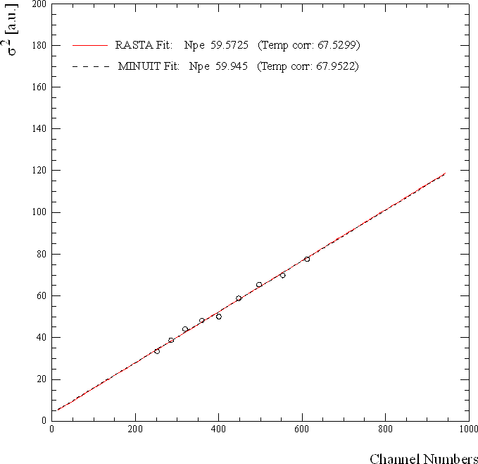
A total of 9 different LED amplitudes were used in data collection with each
CsI crystal, since the variance ( s T) of the photodiode peak
depends on the number of photoelectrons created for unit energy deposition.
Hence
 ,
where E is the LED spectrum peak position, Nph
represents number of created photoelectrons per unit deposited energy, and
s i are assorted variances, such as instabilities of the LED
driving voltage, temporal pedestal variations, etc[16]. The measured points are fitted with a linear function
and such the number of photoelectrons per MeV for each CsI crystal was
established. That number varies from 40 to110 photoelectrons/MeV.

Figure 3-13 Obtaining the number of photoelectrons by the slope of LED
amplitude variances. The offset from zero is caused by noise sources different
from Poisson statistics.
The
use of quartz window PMTs is mandatory due to the low emission wavelength of
the scintillator crystals. In order to accomplish linearity and gain-stability
3 inch EMI 9822QKB and 2 inch EMI 9211QKA phototubes are used for the readout
of the CsI crystals. They offer good quantum efficiency and linearity over the
full dynamic range of the calorimeter using a properly designed voltage
divider[17]. SbCs dynodes have been chosen to
reduce rate dependent effects of secondary electronemission. These effects can
be caused by ion migration or direct impact heating [Smi95].
We used Dow Corning's Sylgard 184 for the permanent attachment of the PMT to
the crystal. Sylgard 184 is an Polydimethylsiloxane (PDMS) elastomer that is
cured by an organometallic crosslinking reaction. After curing it provides a
hydrophobe rubber film with good transmission of UV light. The siloxane base
oligomers contain vinyl groups. The cross-linking oligomers contain at least 3
silicon hydride bonds each. The curing agent contains a proprietary
platinum-based catalyst that catalyses the addition of the SiH bond across the
vinyl groups, forming Si-CH2-CH2-Si linkages. The multiple reaction sites on
both the base and crosslinking oligomers allow for three-dimensional
crosslinking [Cam97]. One advantage of this type of addition reaction is that
no waste products, such as water, are generated. Curing agent and Sylgard were
mixed for the application in a weight ratio 1:8 and pre-processed in vacuum.
The yet bubble-free viscoseus mixture was poured on the PMT. Then in a
dedicated frame the PMT was slightly pressed onto the rear face of the
crystals. Due to adhesion it couples the quartz-glass to CsI; hence the
phototube can be removed by applying strong shear forces. After ca. 24 hours of
hardening the film offers mechanical and optical properties that are stable
over time.
[16] The presence of the so-called excess noise
would add a linear term to this formula (the `Fano factor' F). For a LED
the assumption F-1=0 is sufficiently accurate.
[17] The voltage dividers are designed and
built by B. Stephens from UVA


 ,
,


 ,
,


